Plant Extension
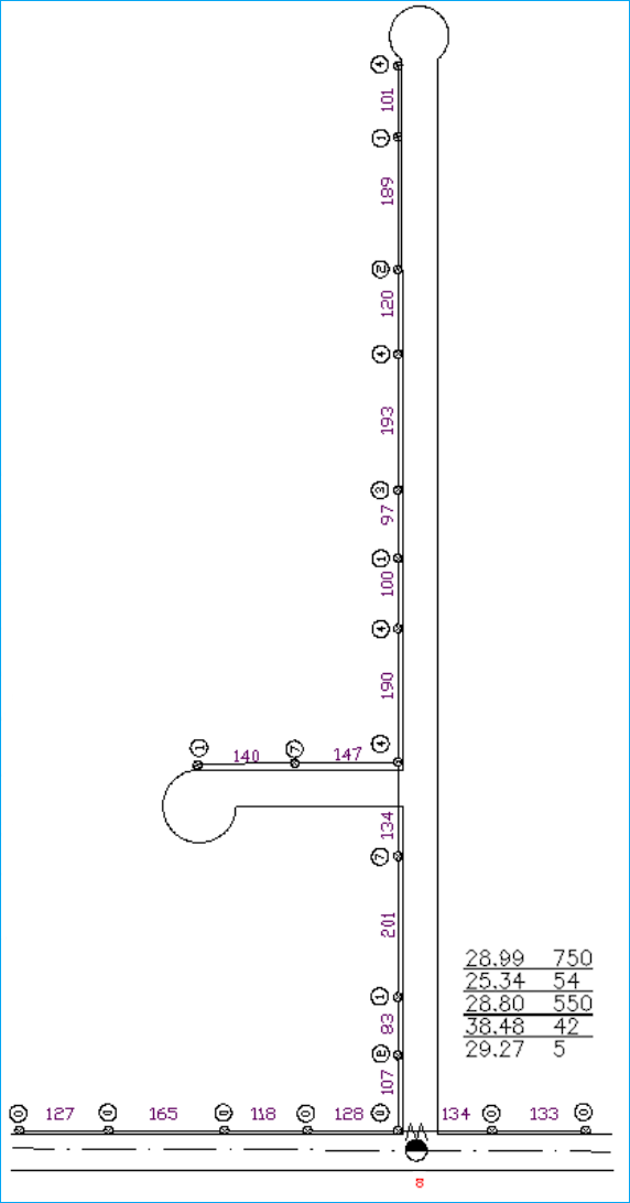
This tutorial simulates a typical plant extension. In this case, we will assume that you do not have the original network in Design Assistant format. Therefore, we will be starting the network with signal levels coming out of a terminated DC 8 saved for this future extension. In this particular project we will be displaying the signal levels at 860, 54, and 550 MHz for the forward path and 42 and 5 MHz for the return path. This tutorial refers to the map found in the image below. It may be helpful to refer to this map as we go along. If you have not yet done so, start the Design Assistant by double clicking the Design Assistant icon.
Project Settings
A new project setting should be created for this plant extension tutorial. If you have not created a Design Assistant Project (DAP) before, please see and complete the Getting Started - Project Settings section before proceeding with this lesson.
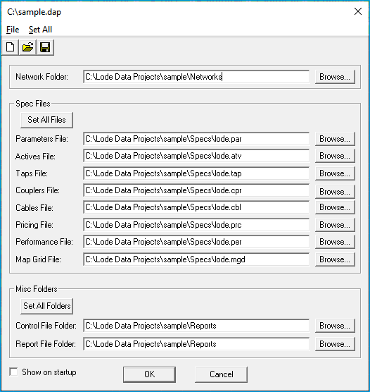
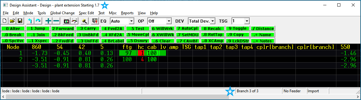
The Design Assistant Project Settings simply tells the Design Assistant where to look for files and where to save files. The project settings dialog will appear automatically when the Design Assistant is started. If the Design Assistant is already running, go to the File pull-down and select Project Settings to display the project settings dialog box.
For the purposes of this tutorial, we want to open the LodeXX.DAP project file that was installed with the other sample files. To open the project file click on the open folder icon and browse to C:\Lode Data Projects\ and double click on the LodeXX.DAP file.
XX
The XX represents the Design Assistant version currently installed. These values are updated with each release to match the product version.
If the DAP file doesn't exist, create a new one and match the settings below.
The Project Settings dialog should look like this:
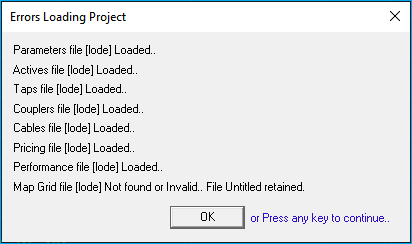
Pressing OK sets the project settings paths and loads the specification files. Depending on the previously loaded project, you may or may not see the following window. If you do, press any key to continue.
Sample Files
The screen shot uses a sample.dap file, however; it's just been renamed from LodeXX.DAP.
If during setup you chose to skip installation of the sample files you can re-install the program and select the location to install them or you can download them from the Lode Data Products Download page.
If during installation you chose to install the sample files to directories other than the specified default directories, then you will need to enter the names of those directories in the Project Settings dialog box. Remember to save the Project file with the new path.
Starting a New Network
To start a new network, press the  icon in the upper left corner of the toolbar or go to the pull-down menus and select
 File -> New -> Network.
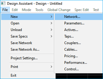
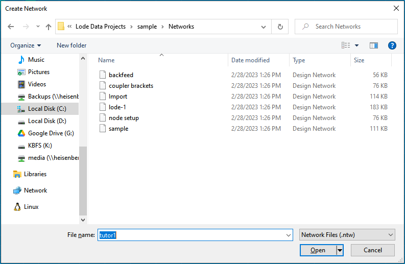
This will display a Create Network dialog box asking for a network name, type tutor1 and click Open.
The Keep Existing Levels dialog box appears as shown:
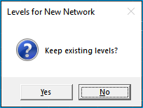
For this tutorial, press No. The Design Assistant should display the Network Initialization Window next. This is used to set starting signal and/or distortion levels for the network. Since we are starting this network from an existing DC 8 with the levels noted on the map, we will need to customize the levels here. To customize the levels in this window, you must first tell the Design Assistant you are not creating a feedermaker network. Before proceeding in this window be sure your NUM lock is on.
Keep Existing Levels
Keep Existing Levels in the new network window will also start a new network, but it will retain any network specific tap output levels set in the previously designed network. It is very unusual to create network specific tap output levels, so that topic is not covered here.
- Uncheck the
Feedermaker Networkcheckbox. - Change
Amp Cascadevalue to1 - Change
LE Cascadevalue to1 - Click on the level next to
860to highlight it blue and then change it to28.99 - Change
54to25.34 - Change
550to28.80 - Change
42to38.48 - Change
5to29.27
The Network Initialization Window should look like this:
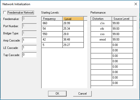
Click OK and you are ready to enter footages and house counts.
Feedermakers
Feedermaker levels are defined in the spec files, and therefore, are not user modifiable. Feedermakers are not widely used in todays networks and are mostly a legacy feature.
Save Network
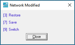
Save this network now so that you have a clean restore point if you have any issues during this tutorial. The quickest way to save a network is to use the network modified menu using the 10-key pad.
Press NUM LOCK on the 10-key pad and then 7 to save the network.
ESC also brings up the network modified menu but using NUM LOCK is quicker.
You can also use your mouse to select the save icon  on the toolbar.
Restore Network
Through out the process of designing a network it is important to save and save often. A good rule of thumb is when you have the network working to your liking, save. When you make a change that you want to persist, save. The Design Assistant does not have a "undo" command. That can be a little unnerving to new users, however; we do have a restore function. The restore function will revert the network to the last saved point. This allows the user to make edits and implement design changes while being able to discard those changes by restoring the network to the last saved point.
We will refer to restoring the network in this tutorial often. To restore a network bring up the network modified menu by pressing NUM LOCK or ESC and then select the 3 restore option.
Entering Strand Data
Notice that once a new network is created, the Design Assistant will automatically display the Entry Mode. The Entry Mode is where most people enter all the strand data for a new design. Before we actually enter the strand data, it might be helpful to do a quick review of Entry Mode.
Enter Footages
Please refer to the map at the beginning of this tutorial and let's enter the footages and house counts off the DC -8.
| Footage | House Count |
|---|---|
| 107 | 2 |
Type 1 0 7 to enter 107 feet and then press the period . key to move the cursor into the house count column, type 2 then period . to move to the cable column, then press 0 and then ENTER to enter the first span.
Together the key stroke sequence looks like this:
1 0 7 . 2 . 0 ENTER
Repeat this process to enter other footages and house counts.
Cable Types
It is not necessary to enter the cable type again until it changes. The Design Assistant will use the last value entered until changed.
Referencing the map, continue to enter the following distances and house counts:
| Footage | House Count |
|---|---|
| 83 | 1 |
| 201 | 7 |
| 134 | 4 |
After the 134 feet there is a branch that splits off to the left. It is possible to create this branch now or after the rest of this strand line is entered. It is completely personal preference as to when the branches are entered, but in general it's best to enter a branch or split when you encounter it. This prevents you from missing or forgetting to go back and enter the branch later. So let's create this branch now.
Use the -7 CrAfLst Create After Last Branch command by pressing - 7. This will create a new branch and number it after the last used branch. In this case we only have 1 current branch so this will create branch number 2.
The Design Assistant will respond with:
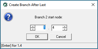
Press OK with the mouse or press ENTER on the keyboard to continue.
Referencing the map, enter:
| Footage | House Count |
|---|---|
| 147 | 7 |
| 140 | 1 |
Now that we've entered the two strand distances and their house counts, We must move back to the previous branch.
There are two methods of doing this:
. ⬆ ⬆ ⬇
The key strokes jump to node 1 of the current branch by pressing . ⬆ and once at the top, the ⬆ up arrow one more time to returns to the parent branch. Then ⬇ down arrow to place the cursor on a blank line in a position to enter the next footage. If you leave the cursor at 1.4 over the current distance of 134', it will be overwritten.
A better and quicker solution is to use the - 3 Return command. The command will "return" to the parent branch and automatically move the cursor to a new line to continue entering information.
Press - 3 to return to the parent branch.
Making sure the cursor is below node 4 on branch 1 (it will soon become branch 1, node 5 or 1.5) continue by entering the following footages and house counts below.
| Footage | House Count |
|---|---|
| 190 | 4 |
| 100 | 1 |
| 97 | 3 |
| 193 | 4 |
| 120 | 2 |
| 189 | 1 |
| 101 | 4 |
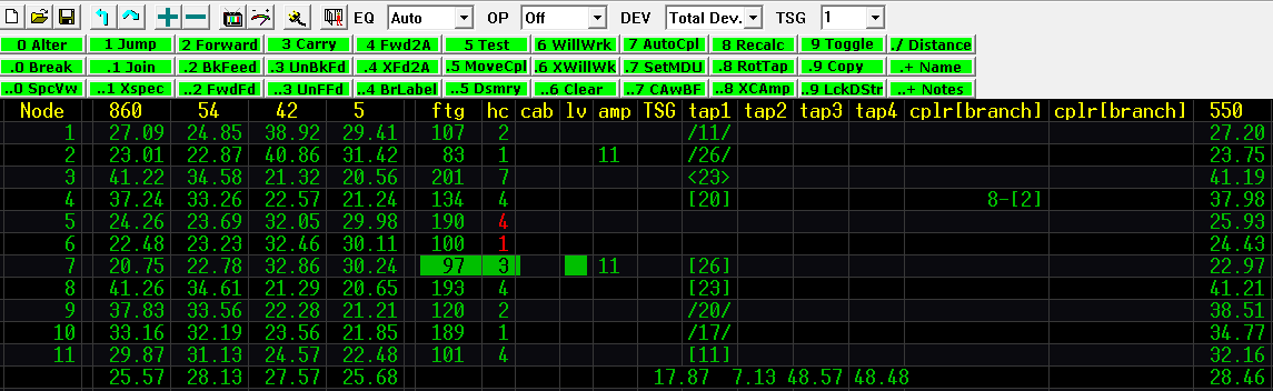
We have made this Design Assistant network reflect the spans and house counts on the map and your screen should look like this:
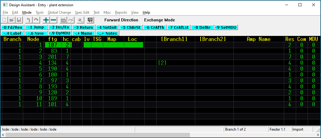
If your screen looks the same, save the network and let's go and design it.
Errors
If your Design Assistant screen does not match the screen above, please start over with enter strand data or you may use the DEL key to delete any extra spans or the INSERT key to add additional spans.
Use . to move columns and change any data that was miss entered.
Use the network modified menu to restore the network to the last saved version if that is a better option. See the restore network section for further review.
Designing the Plant Extension
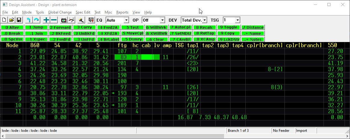
If you are not in the Design mode go to the MODE pull-down menu and click on Design or press ESC 9 to switch modes.
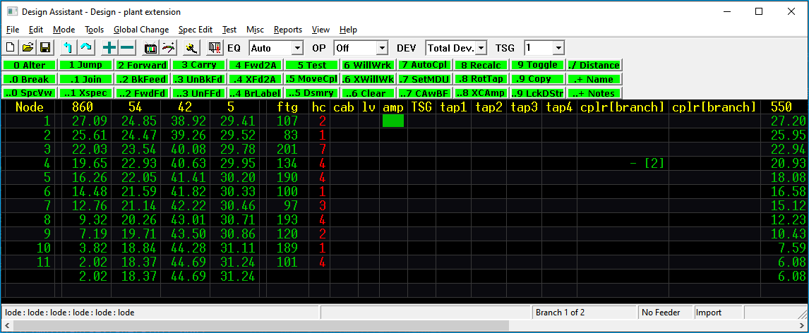
Pictured above is the information we input as seen in Design mode.
Design Mode Review
Review the Design Mode section of this manual if you need a refresher on reading the design screen.
Design Menu
Let's double check on of the Design Assistant's settings before beginning the design.
Set the In-Line EQ selection to AUTO if it's not already selected.
This setting controls the way the program selects in-line equalizers and for our purposes here we want it to select them automatically whenever the maximum crossover is achieved. Therefore, select Auto before continuing with this tutorial.
Design Toolbar Buttons
Review the Design Toolbar for more information on the EQ settings.
Using Will Work
Will Work is a very powerful command that will take the available signal, propagate it down through the remainder of the network and place as many taps as the available signal will allow. It may be the most commonly used command in the program.
Make sure your cursor is at the top of the screen (1.1) and type 6 for Will Work or press the 6 WillWrk button with your mouse.
Two things should have happened:
- It should have placed a 11 two port eleven value tap at
1.1(branch one, node one). - It should have displayed a red message on the bottom status line stating Insufficient signal at 1.2
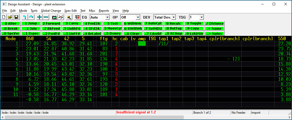
In this case, there was only enough available signal to place one tap.
Mismatch
If your results didn't match, make sure that the signal levels at 1.1 match the above screen shot and that your strand data matches, also make sure your Lode specs are still loaded. If your levels don't match, but your strand data does, go to the Tools pull-down menu and press Network Init. Refer to starting a new network and verify the proper steps were taken.
Placing an Amp
Well, since we are out of signal, the most logical step is to place an amplifier. Since we are just doing a small extension, we will only use line extenders in this tutorial.
Move the cursor to 1.2 (branch one, node two) and put it in the amp column.
There are three ways to place a line extender:
0 Alter
Press 0 to alter the field and then press 1 1 Enter to enter an amp ID# 11 (which in these specs is a line extender).
0 Alter
Press 0 to alter the field and then press Home to display a list of available amps. Using the arrow keys, put the cursor over the 11 type amp and press Enter.
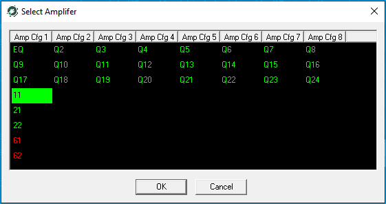
+ Increase Value
Press the + key on your keyboard or mouse click the + toolbar button to enter the first amplifier in the spec file. In this case, this is the quickest and easiest way to enter a line extender, but sometimes it may take several presses of the + key to increment the amp ID# to the desired amp.
Place your line extender using any of the above methods and press 6 for Will Work.
This time Will Work should have placed five taps and displayed a message on the status line on the bottom of the screen stating Missing coupler at 1.4.
Mismatch
If this Will Work did not place five taps, please make sure your strand data matches and that you have the Lode specs loaded.
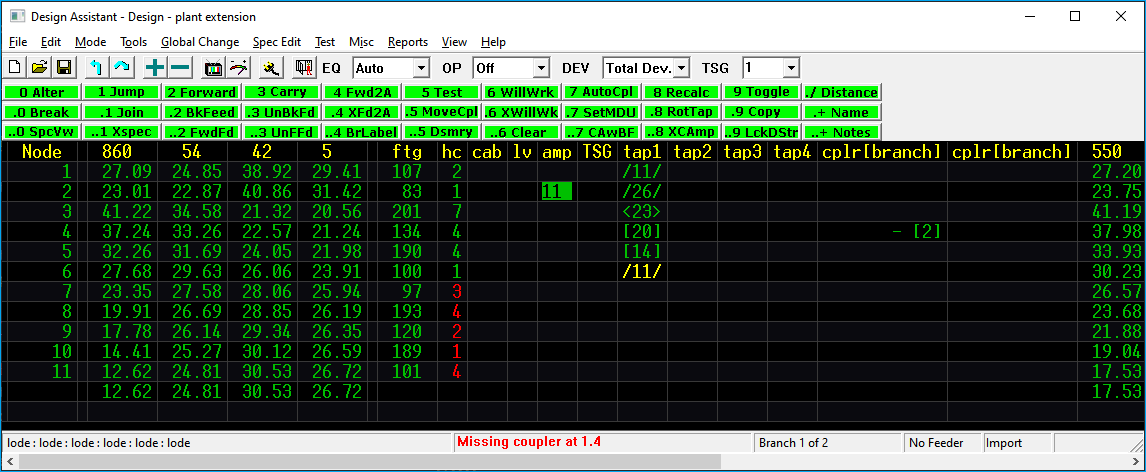
Placing a Coupler
Notice that the Design Assistant's message this time stated that we were missing a coupler instead of insufficient signal. This is because the design cannot continue without a coupler at the branch location. So, let's place one now. Just as in placing amps, there are the same three ways to place a coupler. If you have forgotten the three methods, refer to placing an amp section and place a coupler ID# 2 (two way splitter) and press
6 WillWrk (you will need to have your cursor on node 1.4 in the first cplr column). This time after pressing Will Work, you will notice that the taps downstream of the two way split have changed (this is because we have less signal) and we received a message on the bottom status line stating Insufficient signal at 2.1. Notice that the message looked off-screen to branch 2 first. This is important because, often times, it may tell you something like Insufficient signal at 1.6, this would immediately tell you that branch 2 worked.
Changing a Coupler Value
Well, what should we do now? We know that if we use a two way split, we don't have enough signal to feed branch 2. So, let's change that coupler value to supply branch 2 with more signal. To do this, put your cursor on the two-way splitter and press the - minus or dash key to toggle the coupler value down. Notice this changed the coupler value to an 8-. This signifies a DC 8 with the tap leg (the low leg) coming down the screen that gives us more signal on branch 2 and less on branch 1. Press 6 WillWrk.
Notice that all taps downstream of the DC have disappeared, but that the message box says Insufficient signal at 1.5. This is good, it indicates that branch 2 works. But just to double check, let's jump into branch 2 and see what taps were selected. To go into branch 2, place your cursor on 1.4, press . ⬅ or using the mouse double click the branch number. The Design Assistant should be displaying branch two, which worked with 14 and a 8 tap. Press the up arrow or to return to branch one and finish this extension.
Ok, now that you have changed the coupler value and have at least some working design, let's go ahead and save this network.
Keyboard Shortcuts
Use the keyboard shortcuts whenever possible, it is a little faster because it keeps your hand on the 10-key pad.
Moving an Amp
Ok, the Design Assistant told us that we have insufficient signal at 1.5, so let's put an amp there. Put your cursor in the amp column on node 1.5 and place a line extender with whichever method you prefer. Now that the amp is placed, press 6 WillWrk.
The Design Assistant should have placed 6 taps, but it gave us a message on the bottom status line stating that we have Insufficient signal at 1.11. We almost made it, but we ran out of signal without being able to feed the last tap. It is time to explore our options. It does not look like we will have enough signal to place a four port 8 value tap and stay within our .5 dB tap margin, so that option is out. Well, we could place a third line extender and make it work, but that would not be very efficient design. So, let's try to move the amp down and backfeed a span to see if we can feed this extension with only two line extenders.
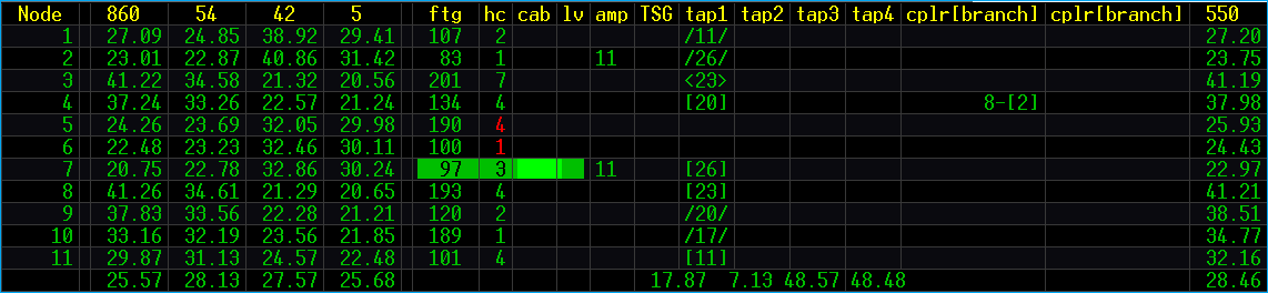
Put your cursor on node 1.5. Press 3 Carry on the 10-key pad or press the toolbar button. Move the cursor down two lines. Notice that the amp moves with the cursor and recalculates the tap values. With the amp at 1.7 it appears that we have enough signal to feed to the end of the line. Press 3 Carry to stop the Carry Amp command.
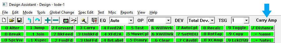
Carry Amp Indicator
As shown in the screen shot above, the toolbar displays Carry Amp. This is an indicator that the Carry function is active. The carry function remains active until the 3 Carry command is pressed again.
Thus to use the carry command press 3 Carry to pick up the active and then 3 Carry to drop or place the active at the desired location.
Your screen should look like this:
Mismatch
If your screen does not look like this, restore your network and start over going back in the steps.
Ok, let's save again before moving on.
Creating a Backfeed
So far so good on designing this plant extension. It looks like the only remaining problem is that there is not enough signal to feed the taps at 1.5 and 1.6. Let's create a backfeed from the amp at 1.7 and see if we can feed those last two taps. Make sure your cursor is on line 1.7 and press . 2 or mouse click on the
.2 BkFeed button. Notice, this created branch 3 and notice that the house count that was on 1.6 is gone.
Leaving your cursor at 1.7, press . 2 BkFeed again to extend the backfeed in branch 3. Below is a quick GIF to follow the steps we just described.
Example GIF
In the example GIF, the mouse clicks on the new coupler (branch 3) that was created using the back feed command and then is clicked on 1.6 to show the house count of 1 is no longer there. This is just to call attention to the changes made by running the command. When going through this tutorial you should keep your cursor on the origin point of the back feed (1.7) and click on .2 BkFeed twice. The back feed command is designed to "walk" back one span each time it is pressed.
Note that the 4 house count that was at 1.5 has disappeared, that is because both of the house counts that were on branch one are now fed from the backfeed branch, branch 3. Notice also that the brackets around branch 3 are curly braces { } instead of the square brackets, this indicates that branch 3 is a backfeed. The - before the { } indicates that no coupler value has been assigned.
Just to double check, with your cursor still on 1.7, press . ⬅ to move into branch 3. Notice that we are going back 97 feet to feed the 1 house count and 100 feet to feed the 4 house count. Also, notice that the cable type changed from 0 to 100 and is displayed in bright green. This category 100 cable signifies cable that is parallel and, therefore, not counted as mileage. It is still cable type 0 or .625 aerial cable, the Design Assistant has simply coded it for bill of materials purposes. The bright green color just helps it stand out as parallel cable, making it less likely for a designer to use it inadvertently.
Custom Cables
Color coding the cables by category (series) is customizable as well defining if a cable type is a parallel, second pass, etc. These settings are outlined in the Cables section.
Press the up arrow to return to 1.7. Put your cursor in the coupler column (on branch 3) and let's define a coupler value. Again, there are three ways to enter a coupler value. Considering that there are four taps downstream on branch one and only two taps on branch 3, it may be wise to place a DC instead of a two-way split. So, place a DC 8 with whichever method you desire (refer to placing a coupler, if needed).
Press 6 WillWrk. Hey, what do you know, a message box we haven't seen yet - Network will work from 1.7.
Ok, go ahead and save again before moving on.
Mismatch
If your screen does not look like this, restore your network and start over going back in the steps.
Testing the Network
It is always a good idea to go to the beginning of your network, press one final 6 WillWrk, and then test it to be sure there are no errors. Press . ⬆ to move the cursor to the top of branch one and press 6 WillWrk.
Good job, Network will work from 1.1 !
Press 5 Test to test the network.
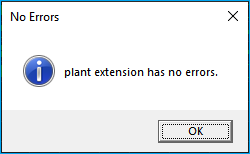
No errors appear in red so this extension is finished, except for one last thing; let's name the amplifiers.
Naming Amplifiers
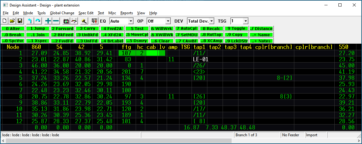
Some people like to name their amplifiers for identification purposes. Place your cursor on the first LE at 1.2 and press . + or mouse click . + Name. This will display the Amplifier Definition window where you can give it a name. Type LE-01 and press Enter. Press Num Lock to clear the amp definition window and this amplifier is named.
Unfortunately, the amp name is not visible because it resides in the same space as the taps. So, to see the amp name, with your cursor in the ftg-hc-cab-lv column, press .0 or mouse click . 0 Break to break the node information into two lines. Notice this will move the LE and tap to a 0 footage line below the cursor location. Move the cursor down one to the node the line extender is on. Press 3 Carry. Move the cursor up one line and press 3 Carry again to toggle off the Carry command. The LE's name should be displayed just to the right of the LE.
Next, let's name the second one. Move the cursor down to the second LE at 1.8 and repeat the process above and we are finished!
One last note, it is probably a good idea to save this network so that all of your hard work is not lost.
Increment Amp Names
After you give an active a name it is not necessary to type in the full name. Usually actives are named sequencially. The Design Assistant will retain the last name used for an active. You can simply hit the + key to increment the value.
Your screen should look like the following:
Congratulations on your first successful design! Believe it or not, this short tutorial has provided you with most of the information needed to create, design, and optimize all types of networks within the Design Assistant.