Actives
Select actives from the Spec Edit pull-down to display the current Actives file. The Actives file stores all the information about amplifier types, inputs and outputs, pad and equalizer information, power requirements, etc.
Actives
The first tab in the file is the Actives tab. Each column on this tab is described below.
Inputs / Outputs
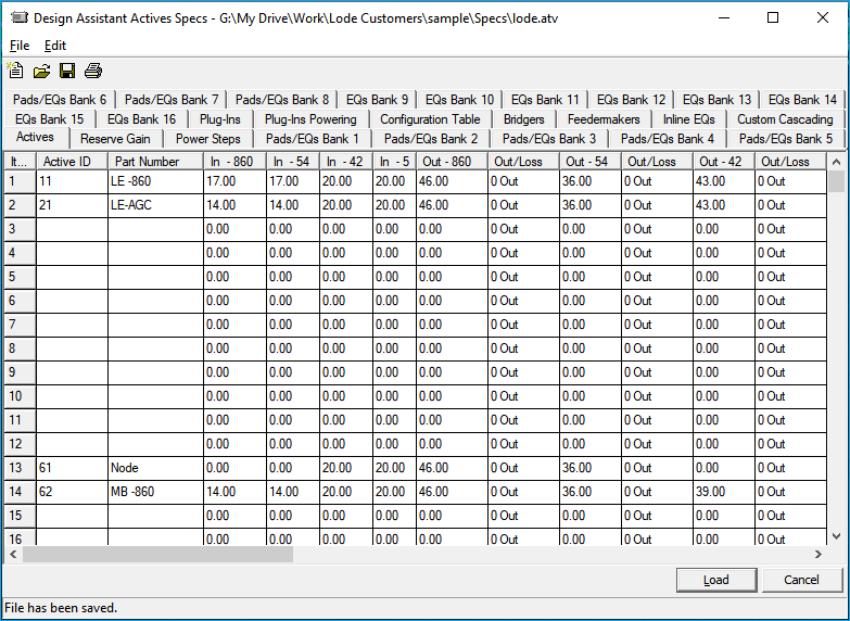
The Actives tab in the actives settings (.atv) file defines the signal levels required at the forward and return inputs, as well as the forward and return outputs produced by each active as indicated by the column prefix In or Out.
In / Out Example
The screen shot shows the input/output columns. In - 860 | In - 54 | In - 42 | In - 5 are the input dB values at the given frequency for each device. Extra In/Out levels can be found by scrolling the right.
Forward / Return Pads
Each active can use a pad and equalizer on both the forward and return path. The numbers under the columns marked Fwd Pad, Ret Pad and Fwd EQ, Ret EQ represent which bank of pad and equalizer values each active will reference.
Pads / EQs Banks
See Pads & EQ's Bank 1-Bank 8 to learn more about the pads/eq banks tabs.
Out / Loss
You can set the frequencies to be a loss rather than an output. If the frequencies are set to be a loss, they will not be considered for pads and equalizers. This feature was introduced to handle the retro fit of amplifiers that only amplify certain frequencies and allow other frequencies to pass through with some loss. For most, the default settings out out will not need to be changed.
Part Number
The part numbers for the forward components are named on this page; these part numbers will show up in the Bill of Materials (BOM). You may have noticed the very first column, Active ID. If you would prefer to use your own active ID's, you may input your active ID's on the Configuration Table page and those changes will be reflected here.
Defaults
If you are not using the Design Assistant's default number system, it is sometimes easier to select an active ID while designing if the unused active ID's are removed on the Configuration Table as was done it the spec file shown in the screen shot above. But, if this has not been done, you are probably looking at the Design Assistant's default active ID numbering scheme.
It works quite well for many projects and is described below:
- 11 : Line extender, 1 in cascade, first one.
- 21 : Line extender, 2 in cascade, first one.
- 22 : Line extender, 2 in cascade, second one.
- 31 : Line extender, 3 in cascade, first one.
- 32 : Line extender, 3 in cascade, second one.
- 33 : Line extender, 3 in cascade, third one.
- 11H-31H: Alternate line extenders. The
His commonly used to denotehigh gain. - 61-89 and 41-49: Trunk amps, system amps, distribution amps, fiber receivers, etc.
Defaults not Required
It is not necessary to use the Line Extender cascading convention described above. This is a traditional configuration that allows a user to quickly glance at an ID and know what it is.
All amplifier signal level calculations are performed the same whether they are set up as line extenders (11-33H) or as trunk amps (61-89 and 41-49). Therefore, it is not necessary to place line extenders in the line extender section, but it does have distinct advantages. Line extenders have an automatic cascade checking function that trunk amps do not; however, it is possible to set up custom cascade checking for all amps. Also, by setting up actives in the appropriate sections, the Design Assistant will keep track of the total number of line extenders and trunk amps for BOM and cascade purposes.
Setting Up Active Inputs
As you will see in your operation of the Design Assistant, we handle specifications for amplifier inputs on the forward frequencies in two different pieces. For convenience, we speak of what we call a housing input and a module input below. Housing input refers to the minimum signal level you want to see at the amplifier housing, that is, at the end of the cable going into the amp. Module input refers to the minimum signal level desired after the equalizer and pad, at the amplifier module inside the amp housing. Return amp output specifications are handled similarly.
Let's have a look at a typical amplifier:
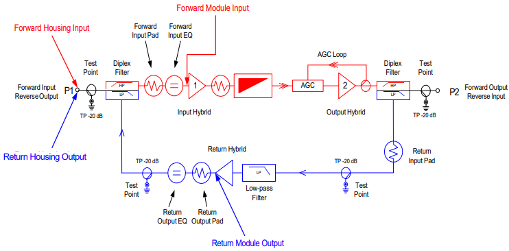
As may be seen, between the Forward Housing Input and the Forward Module Input, we have a test point, a diplex filter and then the input pad and EQ. To properly set up the Design Assistant to choose the correct forward EQ and pad, we need to account for the additional losses we have from the test point and diplex filter. Diplex filters and test point can be set up as a plug-in in the Active spec file. Likewise, in the return direction, we see that we have the return pad and EQ, a test point and the output diplex filter after the return hybrid.
The forward inputs and return outputs on the Actives tab of the actives spec file should be viewed as module level figures.
Actual module input levels are best determined by the amplifier manufacturer, as they will take into account all of the actual losses associated with the internal components. We can, however, get pretty close by using some typical values.
| For the forward | dB |
|---|---|
| Forward Input Test point | 1 dB |
| Diplex Filter Loss | 1 dB |
| Total forward loss | 2 dB |
| For the return | dB |
|---|---|
| Return Output Test point | 1 dB |
| Diplex Filter Loss | 1 dB |
| Forward Input Test point | 1 dB |
| Total return loss | 3 dB |
In addition to the above losses, however, we need to add the minimum high channel loss incurred by the plug-in EQ, which is typically 1 dB.
| For the forward | dB |
|---|---|
| Forward Input Test point | 1 dB |
| Diplex Filter Loss | 1 dB |
| EQ minimum high channel loss | 1 dB |
| Total forward loss | 3 dB |
| For the return | dB |
|---|---|
| Return Output Test point | 1 dB |
| Diplex Filter Loss | 1 dB |
| Forward Input Test point | 1 dB |
| EQ minimum high channel loss | 1 dB |
| Total return loss | 4 dB |
Housing levels are determined for the forward-high and return-high channels by these values to the module level for that device.
For example, assume you have a forward-high-channel module input of 16.50 dB. In this case, your forward-high-channel housing input minimum is 19.50 dB and the Design Assistant would show an error on an amplifier where the forward-high-channel level at the end of the incoming piece of cable is less than 19.50 dB.
Low-channel forward input levels should be set with the output slope you desire in mind. A standardized amount of mid-stage equalization may be accomplished by varying the forward-low-channel input figures by the amount of the mid-stage equalization. Equalization concepts will be dealt with in detail in theEqualization, section later in this chapter.
Padding is done in the Design Assistant after any high and low channel equalizer losses are subtracted from the actual incoming signal levels. Actives are never automatically over-padded.
The columns in between the main frequencies and the extra frequencies labeled Pad Fwd Ret and EQ Fwd Ret, are for pointing an active at a specific group of pads and equalizers to use.
Pads / EQs Banks
See Pads & EQ's Bank 1-Bank 8 to learn more about the pads/eq banks tabs.
Reserve Gain
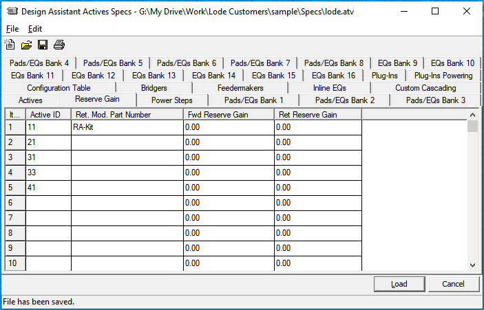
Active ID: This is automatically populated from the values in the Configuration Table tab and cannot be edited from the Reserve Gain tab.
Ret. Mod. Part Number: A return module part number may be entered to be BOMed with each Active ID.
Fwd Reserve Gain: Used to set a reserve gain for the forward.
Ret Reserve Gain: Used to set a reserve gain for the return.
Reserve gain can be thought of as a warning to the designer that he or she is close to maximizing the spacing between amps. If a 2.00 is entered here for an amp with a 17 dB input, the Design Assistant will flag the amp yellow with an input of 17 to 19 dB and red under 17 dB. Note that this level does not actually affect the true gain of the amplifier or the pad and equalizer values chosen for that amp. It is intended as a warning that an amp is down to a two or three value pad for those systems that do not always wish to maximize spacing. The return reserve gain works the same.
Power Steps
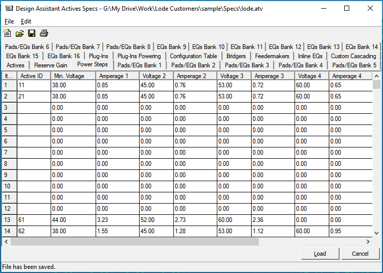
This page specifies powering information for each active. The data are entered in voltage-current pairs in ascending order of voltage for each device. That is, for a given device, from Vmin to V2, it uses A1 amperes; from V2 to V3, A2 amperes are used. Vmin stands for Voltage Minimum and refers to the lowest voltage at which the active will operate. Because actives run more efficiently (have lower current draws) at higher voltages, A1 will be the highest amperage. Not all power steps need be used, but they should be input in ascending order from the left. Powering calculations will be more accurate if more steps are used.
Powering Simulations
For more accurate powering simulations, see Parameters ➡ Powering.
Equalization
Before we continue, let's examine how some of the following equalizer values should be calculated and entered. It is common practice to specify equalizer values in dB of cable and specify that a given equalizer be used if the dB of cable from the previous active falls within a particular range. This comes in quite handy when you are designing a system with 12 channels by hand or possibly with the help of a pocket calculator. Unfortunately, for those of us who are designing cable systems at 550 or 750 megahertz and using real-world equipment that contributes tilt as well, it's a little less appropriate. The next two sections deal with pre-stage and mid-stage equalization. If you are familiar with these two concepts, you may wish to skip to the Pads & EQ's Bank 1-Bank 8.
Pre-stage Equalization
Here we will talk a little about the way the Design Assistant handles signal equalization. If you already understand the general concepts of pre-stage equalization, you might want to skip to the section titledMid-stage Equalization.
Assume you are using a line extender with a 7 dB output tilt -- its output levels might look like this:
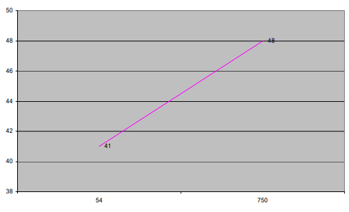
If this LE performs no internal equalization, we would want the slope at the input of the amplifier module (not housing) to be the same as the output slope. Here is how our ideal module input would look:
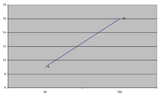
If we had actual signal levels of 20 dB high-channel and 24 dB low-channel at the end of the cable coming into our line extender, the slope of that signal might be visualized like this:
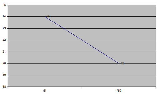
This example shows a negative slope of 4 dB in actual signal going into our LE. To achieve our output tilt, we need to correct that to a positive slope of 7 dB. This means we need to reduce the level of the low channel by a total of 11 dB (knock it down 4 dB to get to a flat slope, then 7 dB more to get to a positive slope of 7 dB). An equalizer that loses 0 dB on the high channel and 11 dB on the low channel would accomplish this.
However, in the real world, equalizers have a small amount of loss at the high channel, too, usually about the same amount of loss regardless of the value of the equalizer. If the real version of our imaginary 0 dB/11 dB equalizer loses 1 dB on the high channel, then it must lose 12 dB on the low channel, to accomplish the 11 dB of slope-change we need.
Methods for EQ selection
The Design Assistant has two methods for equalizer selection; the default mode will never over-equalize, so if you want your equalizers to be selected with a best-fit scenario, be sure to check the Allow Over Equalization button on page 1 of the Parameters.
Mid-stage Equalization
Let's suppose that all our line extenders contained a standardized mid-stage equalizer that accomplished 3 dB of equalization (that is 3 dB of actual slope-change, not 3 dB of cable correction). If we permitted the same 11 dB of equalization to be picked, when the incoming signal reached the mid-stage EQ it would be tilted by 11 dB. Then, the mid stage EQ would add an additional 3 dB of tilt for a total slope change of 14 dB. We would be over equalized by 3.00 dB, and our resulting output levels after amplification would have a slope of 11 dB.
To take this mid-stage equalization into account and let the Design Assistant still pick the proper plug-in equalizer, the amount of mid-stage equalization we expect to take place inside the line extender must be considered in our module input figures. In other words, we must tell the Design Assistant that 3 dB of equalization has already taken place.
The way you would do this in our example is simply by setting the module input figures to 16 dB/12 dB, instead of 16 dB/9 dB. This tells the Design Assistant that we want a module input slope of 4 dB instead of 7 dB. When we run through our scenario of 20 dB/24 dB coming into our LE, the amount of slope-change we need the plug-in equalizer to achieve falls from 11 dB to 8 dB.
To generalize all this in terms of a formula, the plug-in equalizer that meets the following mathematical criteria and results in the smallest non-negative value (assuming the Allow Over Equalization box on page 1 of the Parameters file has not been checked), will be picked:
(actual low input - actual high input) - (low module input spec - high module input spec) - (low equalizer loss - high equalizer loss)
From our example with no mid-stage equalization, when the Design Assistant checks for plug-in equalizers and gets to the 18, 15, 12, and 9-value EQs in our SAMPLECITY Actives specs, the formula will read:
18-value: (24 - 20) - (9 - 16) - (13.66 - 1.2) =-1.46
15-value: (24 - 20) - (9 - 16) - (11.55 - 1) = 0.45
12-value: (24 - 20) - (9 - 16) - ( 9.44 - 1) = 2.56
9-value: (24 - 20) - (9 - 16) - ( 7.33 - 1) = 4.67
The smallest non-negative value here is 0.45, so a 15-value equalizer will be picked. For the example with 3 dB of mid-stage equalization, we get:
18-value: (24 - 20) - (12 - 16) - (13.66 - 1.2) =-4.46
15-value: (24 - 20) - (12 - 16) - (11.55 - 1) =-2.55
12-value: (24 - 20) - (12 - 16) - ( 9.44 - 1) =-0.44
9-value: (24 - 20) - (12 - 16) - ( 7.33 - 1) = 1.67
From this set of results, the Design Assistant will pick a 9-value EQ.
Allow Over Equalization
This example, the 12 value equalizer would be selected if the Allow Over Equalization box has been checked on General Parameters tab of the Parameters spec file.
Pads & EQs
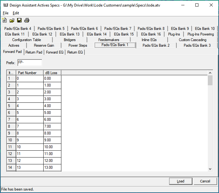
There are 8 tabs to enter pad and eq information. Each tab is grouped into banks and a referred to as Pads/EQs Bank #.
Bank 1 - Bank 8
Each Pads/EQ Bank tab has 4 tabs or pages: Forward Pad, Return Pad, Forward EQ, Return EQ. These four pages/tabs specify the part number suffixes and operating losses of forward pads, return pads, forward equalizers, and return equalizers.
On the first page (actives) of the Actives file, we entered input and output signal requirements for each active device. We also specified from which bank pads and equalizers would be selected. A 1 in the Forward Pad column will allow selection of pads from bank 1, while 2 will allow selection of pads from bank 2, etc. Banks may be mixed freely for each device, giving you the greatest amount of flexibility. If interdiction taps are being used, the program will automatically look to bank 4 to get their equalizer information. If no interdiction taps will be used, bank 4 can be used for normal active pad and equalizer information.
It is important to note that the Design Assistant will never automatically over-pad any piece of equipment when automatically selecting pads. For example, if 1.0 dB of pad is required, a pad of 1.0 dB is selected. However, if 1.6 dB of pad is required, a 1.0 dB pad will also be selected, if that is the closest matching pad not exceeding the amount to be padded. In this instance, a 2.0 dB pad would not be selected. Similarly, the Design Assistant will not over-equalize in normal operating mode (See Parameters: Allow Over Equalization). That is, for a given device it will compare the actual slope at the input of an active to the desired input slope (specified on page 1) of that device and select the largest value equalizer that will not knock the low channel below the minimum desired input.
Equalizers and pads should be entered in ascending order. For example, a zero pad should be on the first line, while the highest value pad should be on the last line. Equalizers should be entered with the highest value cable simulator (if used) entered on the first line working down to a zero, then working up to the highest value equalizer. If no cable simulators are being used, start with a 0 value EQ. Losses for equalizers should be the actual loss in dB at both frequencies.
Pads and equalizers may also be entered with negative loss (gain), but when possible, equalizers should be entered with their actual losses.
Part number prefixes are appended to the pad and equalizer value to create a whole part number for Bill of Materials purposes.
EQs
Bank 9 - Bank 16
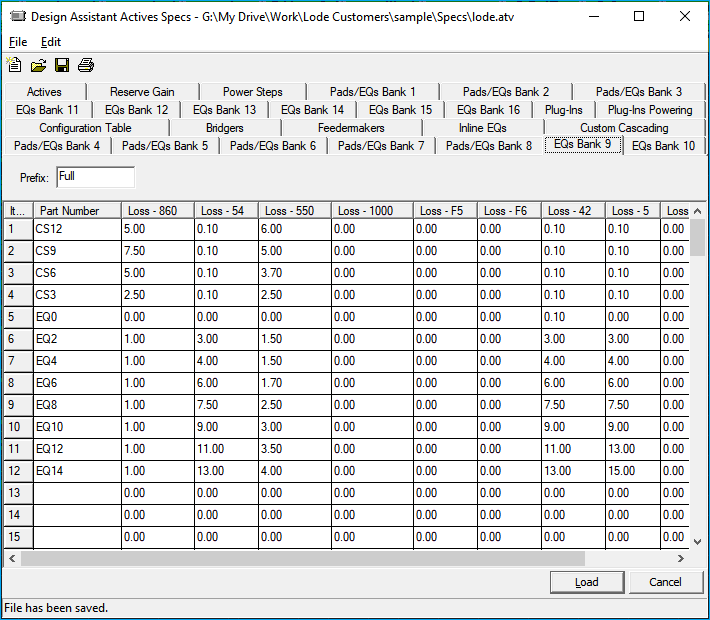
These 8 pages/tabs, one page for each bank, specify the part number prefix and suffix and the operating losses for full spectrum equalizers (equalizers that correct for the entire spectrum - forward and return).
To make taps select these full spectrum equalizers, simply put the bank number (9-16) next to the corresponding tap(s) on the Pad\EQ Banks tab in the taps file. The Equalizers in this section should be entered in ascending order beginning with the highest value cable simulator (if used) working down to a zero and back up to the highest value EQ.
The part number prefix is appended to the part number (equalizer value) for Bill of Materials purposes.
Plug-Ins
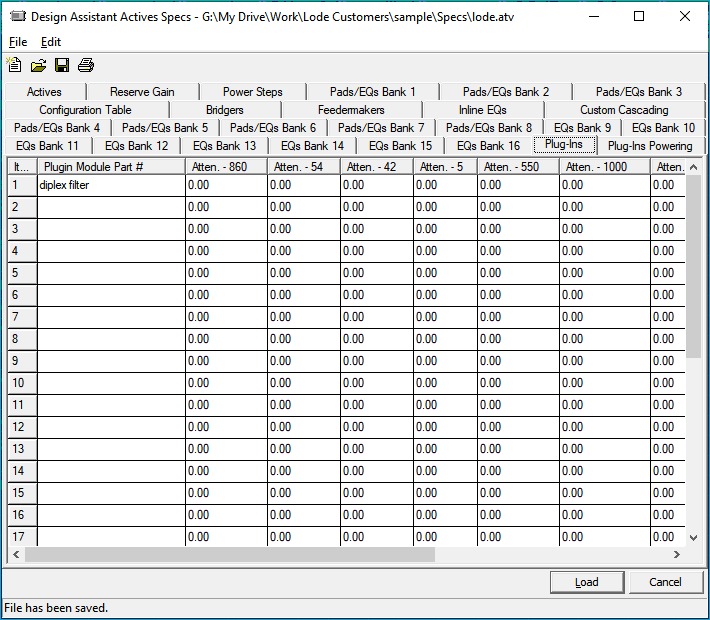
This tab is where part numbers and attenuation values for plug-in modules are entered. It is also where a device can be identified as an AGC device or a step-down transformer.
There is space for up to 31 different plug-in devices with corresponding identification numbers of 1 through 31. The attenuation may be entered as positive or negative values. If entered as a positive value, it will increase the minimum input for the active that it is plugged into it by the amount specified here. For instance, assume an active input of 16 dB and an AGC plug-in module with an attenuation of 3 dB. Once this AGC module is plugged into (see Configuration Table) that active, the minimum input required will be 19 dB. This effectively reduces the gain of that active by 3 dB. If an active's inputs and outputs are set to zero, on page one of the Actives file, it is considered a pass through device. Therefore, adding a plug-in module with 3 dB of attenuation to a pass through active will give you a device that loses 3 dB wherever it is placed.
If the attenuation is entered as a negative value, it will decrease the minimum input for the active that it is plugged into by the amount specified here. For instance, assume an active input of 16 dB and a high gain plug-in module with a negative attenuation of 5 dB. Once this high gain module is plugged into that active, the minimum input will be 11 dB (see configuration table. This effectively increases the gain of that device by 5 dB. It is also possible to set up a gain block type of device that can be placed anywhere, regardless of input, to generate the specified amount of gain wherever it is placed. For example, you could set up a plug-in with a -10 dB attenuation value and plug it into an active that has been defined as a pass through device. This will give you 10 dB of gain wherever it is placed but will not pick any pads or equalizers.
By putting a check mark in the AGC column to the right of the attenuation, you can define a plug-in as being an AGC device. When this AGC device is plugged into an active, the output of that device will remain constant even if slush propagation is activated. With slush propagation turned on, the output of non-AGC devices will vary depending on the input and pad and equalizer selection. For example, assume the minimum input of an active is set up for 16 dB and the actual signal into that amp is 18.8 dB. In this case, the Design Assistant will pick a 2 pad, leaving 0.8 dB excess into the gain block inside the amp. A non-AGC active will then have an actual output that is 0.8 dB higher than is specified in the spec file. With slush propagation turned on, this 0.8 dB will be carried on through the system for downstream pad, EQ, and tap selection. If an active is defined as AGC, the slush propagation will be reset to 0.0 at that amplifier.
A check mark in the column labeled step down will identify this particular plug in as a step down transformer. A step down transformer is a device that will knock the effective voltage level into a device down to levels that the device can handle. This is used mainly if you are powering your system at 90 volts, but some equipment is unable to operate above 60 volts. After marking the device as a step down transformer, enter the desired voltage step down ratio in the first frequency level column (often .66). Then, in the second column enter the current step up ratio (typically the inverse of the voltage step down ratio). When a step down device is placed in the Design Assistant, the voltage will be knocked down to the appropriate levels.
Plug-In Powering Data
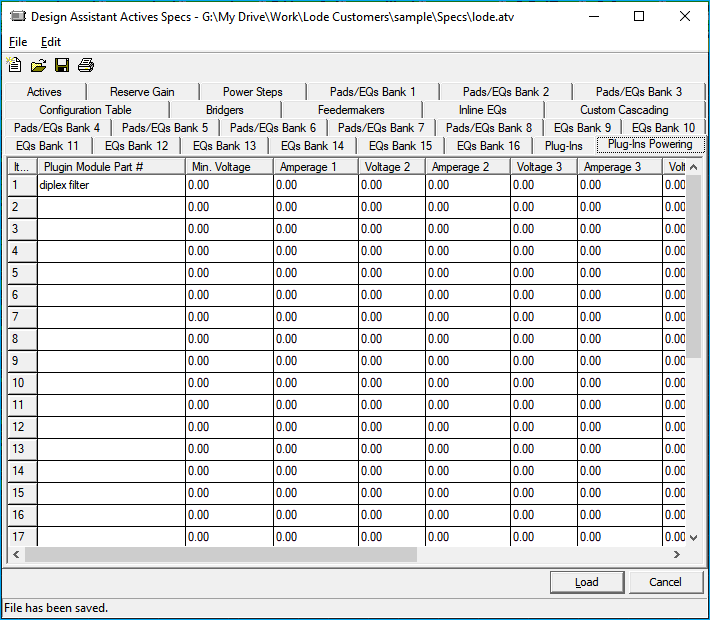
On this page/tab, enter the individual current draws of each plug-in module. These current draws will be added to the current demand of the active devices that these modules are plugged into. The data should be entered in ascending order in voltage and current pairs. Vmin is the lowest voltage at which the module can operate, A1 is the current that the module draws at the minimum voltage. From Vmin to V2, the current from A1 is used. From V2 to V3, the current from A2 is used, and so forth. Not all the voltage current pairs need to be entered. Nor do they need to match the steps for the actives' power draws. Keep in mind however, that the powering will be more accurate as more power steps are filled in.
Configuration Table
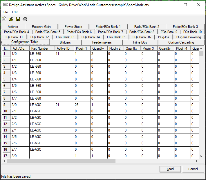
This screen is for the custom configuration of amplifiers. The first column (forward part number), will automatically display the part number entered on the Actives tab and therefore, is not editable here. These part numbers are the description of the base unit amplifiers, to which you may add several plug-in modules.
The column labeled Active ID will automatically display the default identification numbers of each base unit amplifier. If desired, the active ID for any of the base unit actives may be changed or removed. If the active ID is changed, that change will be reflected on all other pages in the Actives file. This new active ID number may be numeric or alphabetic. Note that the alphabetic Active ID is case sensitive. Therefore, you must specify the Active ID exactly as it appears (in upper or lower case) when you enter it into the Design screen. If you do not, you will receive an error message that states ID number not found, Any key to continue.
There are eight separate Plugin and Quantity pairs that allow you to plug-in up to eight different modules into each base unit. The column Plugin refers to the part number defined on the Plug-Ins page. Using a 1 under Plugin will plug-in part #1, while a 2 will plug-in part #2, and so forth. Entering a 1 for the part will cause the attenuation figures for part number 1 (on page 10) to take effect, entering a 2 will calculate the figures for part number 2, and so forth.
A quantity of 1 entered in the Quantity column will add the current draw (of the part entered to its left) to the base unit amplifier's total current draw. It will also add that plug-in to the Bill of Materials. A quantity of 2 will add the powering information twice, the BOM information twice, but only takes out the attenuation once. Therefore, if you wish for the attenuation figures subtracted (or added) more than once, you will need to enter that part number with a 1 quantity as often as desired.
Blank Lines
There are seven blank lines under each part number. This makes it possible to create up to eight custom amplifiers using each base unit amplifier and adding to it virtually any combination of plug-in modules. This makes a grand total of up to 400 different amplifier configurations.
Bridgers\Feedermakers\Inline Eqs
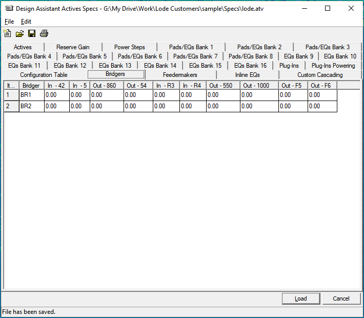
The information about the bridger is entered.
BR1 & BR2: Represent the bridger 1 and bridger 2 levels. These levels are used by the Network Initialization Window anytime a new network is created to set the starting signal levels. It is possible to override these levels while starting a new network, if desired. Bridger module forward inputs and return outputs have no effect on the operation of the design; thus they are not assigned any value here. Please seeChapter 5: Utilities,section Network Initialization Windowfor more information.
Feedermakers
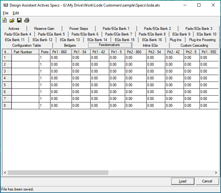
Feedermakers: The feedermaker section allows for definition of the losses for eight feedermakers. Lines one through four are given losses for a feedermaker type 1 (1 port), a feedermaker type 2 (2 ports), a feedermaker type 3 (3 ports), and a feedermaker type 4 (4 ports) respectively. The losses from the first four lines are subtracted from the Br1 level (on page 1 of actives) to supply the correct output levels through the Network Initialization window. The program will then look to this table for the correct number of ports and expect you to specify a name for the networks from each port (if using the parent/child network architecture). The next four lines (5 through 8) are for feedermaker losses that will be subtracted from the Br2 levels. Often, these lines are left blank because the specs only call for one (or no) bridger output. For more information on feedermaker operation and the Network Initialization Window, please seeChapter 5: Utilities,sectionNetwork Initialization Windowfor more information.
Equalizers
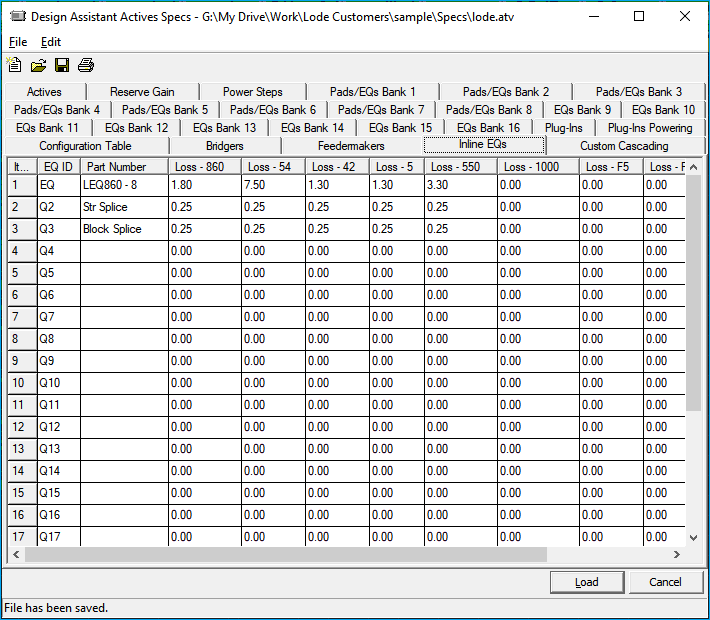
Equalizers: Losses and part numbers for in-line equalizers are entered at the bottom-left part of the screen. The line called EQ should store data about the default in-line equalizer. It is the equalizer that will be selected automatically. The rest are user-definable pieces of equipment (usually equalizers). Signal losses are entered in the corresponding columns. It is possible to give the Q numbers a negative loss that will then be calculated as a gain. All these devices are placed in the amp column of the Design screen.
Cascade Setup
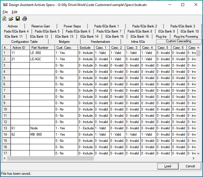
The Active ID and forward module part numbers are there for reference only, thus are not editable from this screen. A check in the Custom Cascade column will turn on the custom cascading feature. A check in each numbered column will make that particular position a valid position in cascade. Place a check in the Exclude column if you wish to eliminate an active from the cascade count.
For example, if Active ID 64 is an AGC amplifier that must be in positions 2, 4, and 6 in cascade, enter a check in the 2, 4, and 6 columns next to Active ID 64. In this case, anytime a 64 type amplifier is used at any other place in cascade it will be flagged with an error message when the test function is used. Note that placing an amplifier at an incorrect place in cascade will not turn the amplifier red or yellow. This custom cascade feature allows for setup of valid cascade positions for up to 19 amplifiers in cascade.