Couplers
Select couplers from the SpecEdit pull-down to display the current Couplers file. The coupler file consists of five pages. Again, just as in taps, the Coupler ID is used for reference by you and the program only, the Coupler ID is never used in actual mathematical calculations. The Couplers file is used to define the characteristics of internal couplers, external couplers, and Network Interface Units.

On this page, all of the specifications regarding couplers are entered. In the leftmost column, enter the part number for the coupler. The part number may be up to 14 alpha- numeric characters. In the Coupler ID column enter the number you wish to use as the ID, that is the number you would like to enter while placing the particular device. It is helpful to use intuitive Couple ID's, for instance 2 for a 2 way splitter or 8 for a DC 8. Though it is possible to enter an ID number with a decimal value, for example 3.5, in the specification file, the Design Assistant will not recognize a 3.5 as being a valid Couple ID number when the coupler is placed during the design process. Therefore, it is recommended to enter all Couple ID numbers as whole numbers.
In addition to defining the losses of each coupler and the number of tap legs, you also define whether or not each coupler is an external, internal, or optical coupler on this page. To define the coupler as being an external coupler, do nothing more than enter the losses and the number of tap legs. To define a coupler as an internal coupler, place a check in the int column on the far right. A coupler defined as an internal coupler will be treated differently by the Design Assistant in two ways: 1. The Design Assistant will not BOM any fittings in conjunction with an internal coupler. 2. The Design Assistant will flag an internal coupler red if it is used incorrectly, that is, not placed at the same location as an amplifier or placed with a tap or cable footage in between the amp and the coupler.
To define a coupler as an optical coupler, place a 1 in the Optical column. Once identified as an optical coupler its losses may be entered as a percentage rather than a discreet dB loss.
The next columns labeled Tap are used to enter the tap leg losses at the forward high, forward low, return high, and return low frequencies, respectively. The four columns to the right of that labeled Thru are used to enter the thru leg losses at the forward high, forward low, return high, and return low frequencies, respectively.
In the next column, labeled Tap Legs, enter the number of tap legs available for the coupler.Note: the Design Assistant will create a branch for each tap leg and the Design Assistant can only create two branches at any one location. Therefore, the maximum number of tap legs should be 2 (as in the case of a 3 way splitter), except for the case of a drop splitter. When entering drop splitters into the Couplers file, they should be placed following a blank line so that they will not be selected automatically to feed a regular branch. It is not necessary to enter the Thru Leg specification (because a drop splitter has no through leg). The number of Tap Legs should be the number of output ports on the drop splitter, that is, an eight-way drop splitter should have eight tap legs.
In the remaining columns enter the tap and thru leg losses at all the extra frequencies that have been enabled in the Parameters file.
Defining Amplifier/Optical Receiver Couplers
Many of today's amplifiers and optical nodes have multiple outputs but do not use feedermakers as the older mainstation-type amplifiers did. Because of this, we need to be able to tell the Design Assistant how to choose the individual legs of each device. To do this, we will define a branch (at the amp's location) by using special couplers.
Let's take a look at some typical equipment configurations and determine what type of coupler to define:
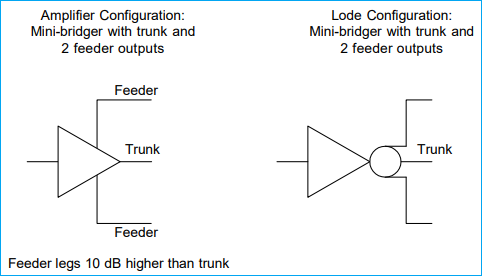
Three-port mini-bridger with a trunk level output and two feeder level outputs
- Define the amplifier (low level) trunk output in the Actives spec file.
- Define a 3-way, unequal splitter with zero loss on the through leg and negative amounts on the tap legs.
- This will make the two feeder legs a higher level.
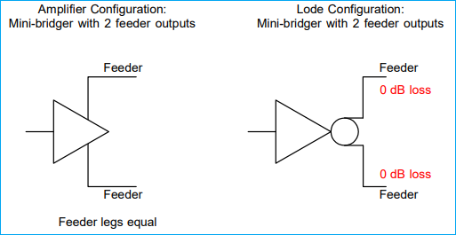
Two-port, equal output mini-bridger or dual-driven output line extender amplifiers
- Define the amplifier output in the Actives spec file.
- Define a 2-way, no loss splitter.
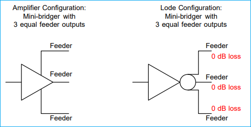
Three-port, equal output (balanced triple) amplifier
- Define the amplifier output in the Actives spec file.
- Define a 3-way equal, no loss splitter.
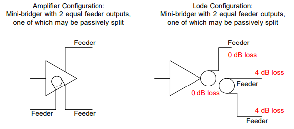
Three-port mini-bridger with a default of two equal driven ports, but the ability to passively split one port
- Define the amplifier high level output in the Actives spec file.
- Define a 2-way, no loss splitter.
- Define an additional 2-way splitter (or couplers as appropriate) with a positive amount of loss E.g. an additional splitter with +4 dB which will then be subtracted from the high level (un-split) output to give the two lower level outputs.
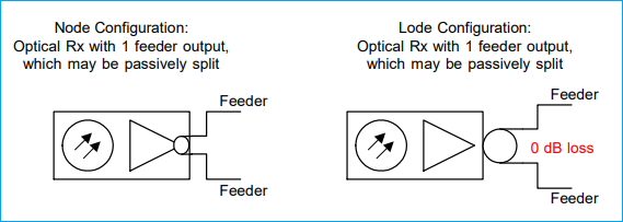
Optical Nodes
For optical nodes, let's create a one-port, internally passively splittable node
- Define the node high level output in the Actives spec file.
- Define a 2-way splitter with a positive amount of loss.
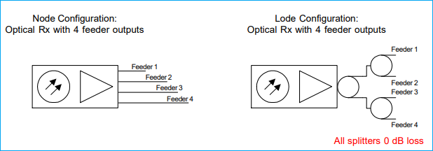
For a four-driven-port node:
- Define the node high level output in the Actives spec file.
- Define three 2-way loss less splitters.
You need three splitters as the first feeds the other two to give you four equal outputs.
Base NIUs
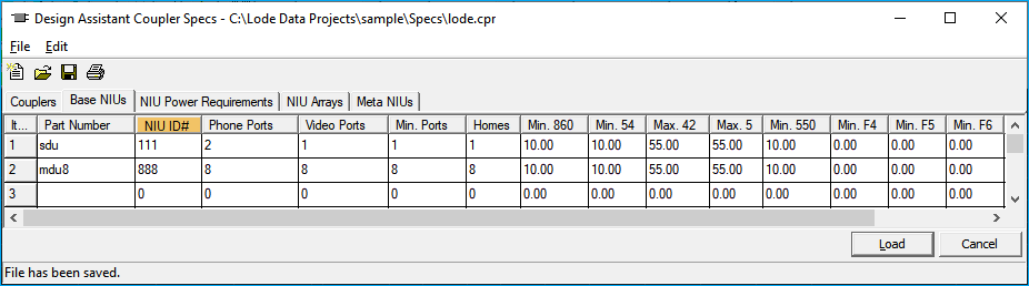
This page defines physical characteristics and signal level requirements for base NIU types. An NIU (Network Interface Unit) is the on-premises device that both separates and multiplexes the broadband video and telephony signals. The NIUs are defined in the Couplers file because for design purposes all NIUs except the default (see NIU Arrays) are placed in the coupler column in the MDU window.
Part number: Specifies a part number for the NIU. There is a maximum of 31 NIU part numbers and they may be up to 14 alphanumeric characters.
NIU ID#: A three digit numeric code used to identify the base NIU types that can be configured into NIU arrays on the NIU Arrays page. Please note that this ID number is only used on the NIU Arrays page to configure NIU arrays -- it is not input directly into the MDU window. This code can be one, two, or three digits, but it should not duplicate the ID numbers entered for couplers on other pages.
Ports--Phone: The number of phone ports available to this NIU. The Design Assistant will use this number when the NIUtest function is invoked from the Powering menu. The NIUtest calculates power consumption based upon various scenarios to help determine possible powering conditions.
-
--Video: This feature is for reference only, the number entered here will not affect any powering calculations.
-
--Min.: This represents the minimum number of phone ports that are actually expected to be hooked up at this type of NIU. For example, assume an NIU has 8 phone ports available with a minimum of 3 hooked up at any one time. For powering purposes, this NIU will be assumed to have no less than 3 and no more than 8 phones hooked up. The additional line percentage specified on the General Parameters page of the Parameters file determines the probability of each additional line over the minimum of 3 to be hooked up at any given time.
Homes: This is the number of dwelling units that can be covered by this type of NIU. If the sum of the house counts defined for the NIUs used in an MDU window is less than the house count specified at that particular node, it will be flagged as an error. For example, if two NIUs are required to design an apartment building, and the house counts that they can feed are 3 and 5, then together they can feed up to 8 units. Therefore, if the house count listed in the house count column of the Design screen is greater than 8, the house count itself will be displayed in red. You will also receive an error message from the test function that says, not enough drops at node x.x where x.x represents the location of the MDU window.
Minimum and Maximum: These are the minimum forward input and maximum return output signal levels for the NIU. For any node with an MDU window that contains NIU array codes in the cpl column, taps will be selected to provide sufficient signal (at the end of the drop cable) for the levels specified here. The requirements for all individual NIUs comprising the arrays will be used to calculate the tap values at such a node. In this case, the lv columns both in the MDU window and in the Design mode will be ignored.
For any node without an MDU window, the value listed in the lv column in the Design screen will override the signal level requirements listed for the individual NIUs that comprise your default NIU array. Therefore, if the default NIU does have signal level requirements, it may be desirable to set up the tap output spec so that the level at the end of a typical drop is the input to the NIU, not the level at the TV or converter.
These levels need not be used unless desired. If there are no minimum/maximum levels input here, then the Design Assistant will pick taps based solely on the number entered in the lv column either in the Design mode or the MDU window.
NIU Power Requirements
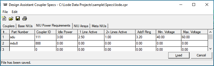
This page is devoted to the power requirements of Network Interface Units. Note the power here is expressed in watts as opposed to voltage as in other parts of the program. Part numbers and ID numbers are copied from the previous page and are not editable here.
Idle Power: Number of watts required to power the NIU in its idle state (no lines active).
1 line active: The Additional power required when 1 line is active or off-hook. This is added to the idle power when 1 phone is activated.
Addl line active (ea): The incremental increase in power required for each additional active line when one phone is already off-hook.
Addl ring power (ea): The additional power needed for each phone that is ringing, over and above the power needed when that line is active.
Minimum voltage: Minimum operating voltage of the NIU. When the voltage at the NIU node drops below this value, it will be flagged by an error message in the test function that says insufficient voltage for NIU.
Power Values
All power values on this page are incremental. For example, if a given NIU type had ten lines, five of which were off-hook and two were ringing, for a total of seven active lines at a particular point in time, the power required would be:
(Idle power) + (1 line active) + [(7 active lines - 1) * (additional line active power)] + [(2 ringing lines) * (additional ring power)] = total power required
NIU Arrays
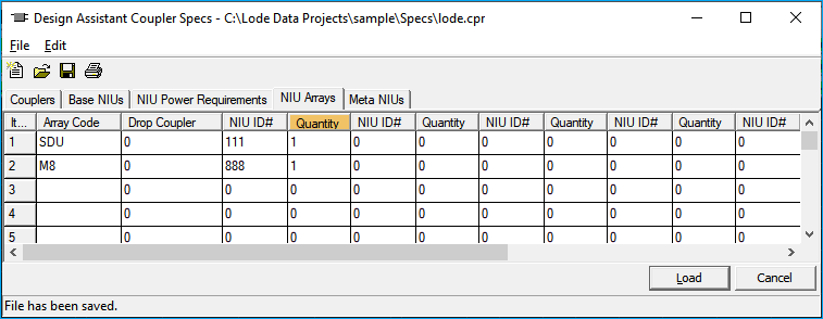
This page creates arrays of NIUs by grouping individual NIUs. These arrays help provide the flexibility necessary to feed any type of home, apartment complex (MDU), or business. The array defined here may consist of only one base NIU or virtually any combination desired, but they must be defined on this page. Note: The NIUs defined on pages 2 and 3 are not functional until they are placed into an array on this page. The Design Assistant will not recognize the NIU ID numbers defined on page 2; it will only recognize the Array code defined on this page as an active NIU. The array that is defined on line 1 will be considered the default NIU. The default NIU will be placed at the typical house count, that is, any node that is not further defined by an MDU window.
Array code: Three-character alphanumeric code used to identify the NIU array being defined. If the array code is entered as a +, the information on that line will be considered a continuation of the line above. Each line entered to define one array will use a separate drop, that is, an NIU array code followed by three + lines will take four separate drops. Do not specify an array code that is identical to a coupler ID #, as this will prevent the selection of that coupler in an MDU window and is likely to cause confusion. To place a particular array code, other than the default on line 1, open the MDU window at that node and place the desired array code in the cpl column.
Drop coupler: Enter here the three-digit Coupler ID# (from the Couplers page) for any drop coupler that will be used to feed the individual NIUs specified on this line. It is possible that NIU devices may exist that can feed signal directly from one to the next, so that no drop coupler is needed when feeding an array of multiple devices. Therefore, this column may be left blank even if there are multiple individual NIUs specified in the NIU ID#/Quantity columns. In most cases, however, a blank drop coupler column will indicate only a single NIU in the NIU ID#/Quantity column. In this case the drop will feed directly into the NIU specified on this line.
NIU ID#: Enter here the ID number for the individual NIU(s) to be configured in this array. This is the three-digit ID number that was entered on the Base NIUs page while defining the individual NIU characteristics. It is possible to feed up to eight individual NIUs in this array from one drop. If your array is made up of NIUs fed with separate drops, you will need to place a + in the Array code column on the next line, and continue your configuration there.
Quantity: Enter the quantity of NIU devices of the type specified in the preceding part column that you wish to comprise this particular array. There is a maximum of 255 in the Quantity column, which we hope will be more than enough for anyone.
Meta NIUs
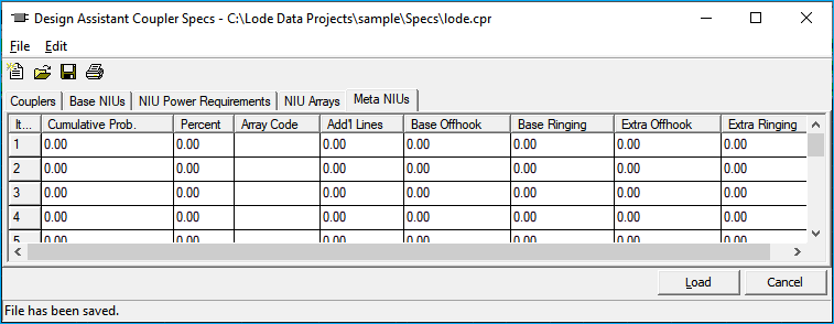
Meta-NIUs are used to describe telephony usage patterns. While the previous three pages specify the physical characteristics of NIU devices and arrays of NIUs, this page describes how customers use their telephone. Meta-NIU setup is similar to the NIU Array setup on the previous page. In this case, however, multiple NIU arrays are grouped together further describing the customer usage patterns. The use of Meta-NIUs can be toggled on or off from the NIUTest function within the powering menu.
NIU Powering
See NIU Powering Analysis for more information on how to use Meta-NIUs.
Cumulative Prob: A read-only column displaying the accumulated percentage totals already entered in the unit column. If the cumulative percentage is already at 100% and more unit percentages are added, then all usage patterns entered hereafter are ignored by the powering analysis routines. A cumulative percentage of less than 100% is acceptable. In this case, the remaining percentage of customers will be treated as a portion of the total Penetration percentage (entered on page one of the Parameters file).
Penetration %
Penetration % is still in effect with Meta-NIUs toggled on during powering analysis.
Percent: The percentage of the overall customer base expected to fit the usage pattern described by the entries on the remainder of this line.
Array code: The NIU array code (defined on the NIU Arrays page of the Couplers file) expected to be used by the percentage of the customer base defined on this line.
Add'l lines: The percentage of customers defined by the particular NIU array code that are expected to purchase an additional phone line. This entry is similar to the additional line percentage set on page one of the Parameters file except here it is used to describe the phone usage pattern for this group of customers.
Base OffHook: This is very similar to the off-hook percentage entered on page one of the Parameters files in that it describes the percentage of time a phone line is expected to be active. In this case, however, it refers only to the base phone line described by the minimum column on page 2 of the Couplers file. In addition, it refers only to the customer type defined on this particular line. Separating the base lines from the extra lines (additional lines) further refines the customer usage description since different customer groups may use the base lines quite differently than they use their additional lines.
Base Ringing: The percentage of time that this customer type's base line phone is expected to be in a ring state.
Extra OffHook: The percentage of time that this customer type's additional line(s) is expected to be in an active state.
Extra Ringing: The percentage of time that this customer type's additional line(s) is expected to be in a ring state.