Starting the Program
![]()
To start the Design Assistant, simply double click on the icon the install created. This executes a file called DAPCxx.EXE which, by default, resides in theC:\Program Files\Lode Data Corporation\Design Assistant\xx directory.
XX
The xx represents the Windows operating system architecture. For example, DAPC32.EXE is the executable for the Design Assistant Version on a 32-bit architecture.
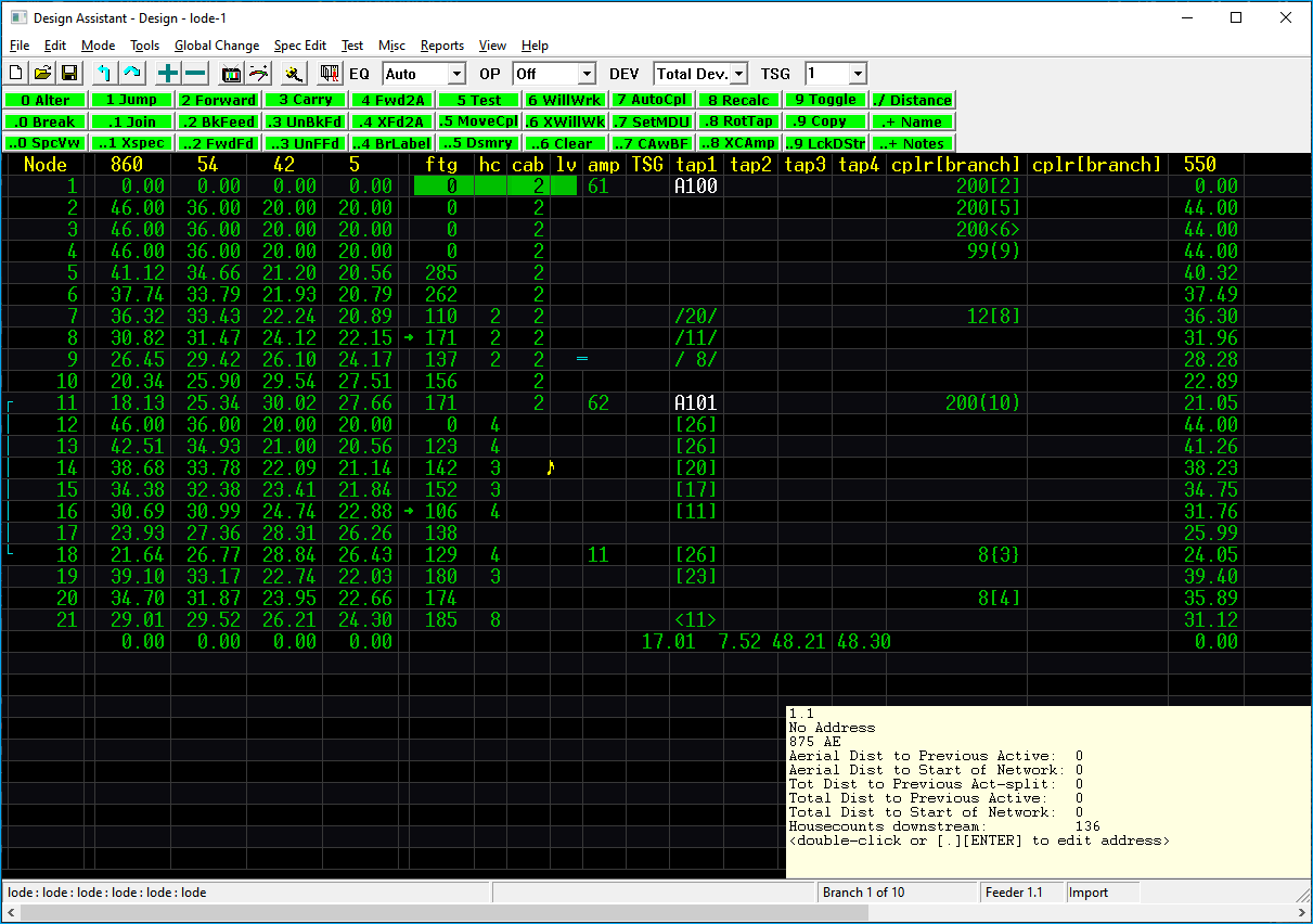
When started, the Design Assistant displays the Design Mode and you are ready to design.
Menus
Now that the Design Assistant is installed and running properly, you have hundreds of powerful commands at your fingertips.
The Design Assistant uses two kinds of menus:
- Pull-down
- Screen menus
The pull-down menus is accessible with the mouse or by holding down the ALT key and pressing the underlined letter in the menu
For Example:
ALT F will pull-down the File menu.
The screen menus are accessible by pressing the keystroke or series of keystrokes listed on the menu before the command name or by left mouse clicking on the menu buttons.
Commands are immediate
Most commands are immediate and therefore don’t require an Enter ⏎.
The Design Assistant’s screen menus are split into four categories:
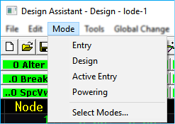
DESIGN- Where the actual design is performedACTIVE ENTRY- Where the actual design is performedENTRY- Where strand/route data is entered into the programPOWERING- Where all network powering takes place
The screen menus, while not always as easily readable as the pull-downs, are an incredibly powerful part of the Design Assistant because they enable the use of the 10-keypad to invoke Design Assistant commands. Once familiar with the menu system and proficient with the 10-key, there is no faster way to do design!
Screen Menu Categories
Screen menu categories are also referred to by MODES because they can be found under the MODE pull-down menu.
Project Settings
For the purposes of the Design Assistant, the Project Settings are used to define paths to
different directories. Project Settings is a file that stores the paths defined within in it. The Project Settings file has a file extension of .DAP. This stands for Design Assistant Project.
Paths
A “path” on a computer is the letter of the hard drive followed by the main directory and subdirectories.
C:\Lode Data Projects\Specs is an example of a “path” where \Lode Data Projects is a main directory and \Specs is the sub directory of \Lode Data Projects on your C: drive.
The Project Settings sets all the paths so that the Design Assistant knows what directories to save files to and open files from. The Design Assistant needs to access a few different kinds of files to operate. It also creates different types of files during normal operation.
Due to the various kinds of files and the sheer number of files that can accumulate over the years, we recommend storing and writing these files in separate sub directories on your hard drive. Often times the best way to do this is to store your files per project.
For example, you may wish to setup separate sub directories for each project using the project name as the directory name.
Below is an example of a recommended directory structure:
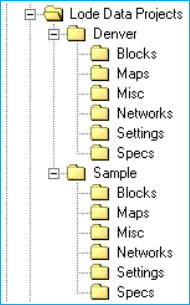
Lode Data Projects: This is the main directory where we will store all of our projects
Denver: This is a sub-folder of Lode Data Projects. This is a project where we will store all of our files for our Denver project. This directory has many sub-folders as well. Networks, Specs, and Misc are all directories we will use for The Design Assistant.
Sample: This is a sample project. These are our sample files we installed during setup. Notice the directory structure is the same as Denver.
Setting up your project settings paths properly will ensure that the Design Assistant will always be able to find the desired specification and network files and help with effective file management.
Recommended
This is a recommended directory structure only. You can save the files in any manner you choose.
Setup
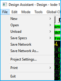
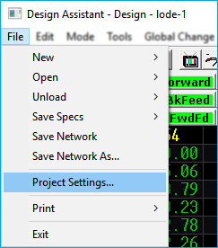
To set your directories, select PROJECT SETTINGS from the FILE pull-down menu.
FILE --> PROJECT SETTINGS
Displayed in front of you are eleven path options:
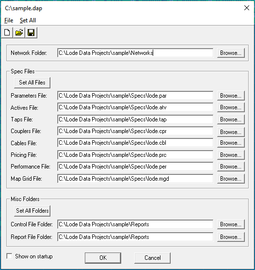
- Network Folder: Path where you will save your network
.NTWfiles - Spec Files: Paths of your specification files
- Parameters File:
.PAR - Actives File:
.ATV - Taps File:
.TAP - Couplers File:
.CPR - Cables File:
.CBL - Pricing File:
.PRC - Performance File:
.PER - Map Grid File:
.MGD - Misc Folders: Miscellaneous files or Reports folders
- Control File Folder: Path
- Report File Folder: Path
Version 11
Version 11 introduced a PCD folder option under the Network Folder:. This was introduced so users can specify the location of PCD networks if they are not located in the same folder as the Network Folder. In most cases the PCD files should be stored in the same path as the networks.
If your directory structure is setup so that all files are stored in the same directory, it is best to use the SET ALL FILES option to set all paths to the same directory. If, however, your file management plan is to keep different types of files in separate subdirectories, it may be necessary to set your Project Settings paths individually.
Set All Files
Your spec files must all have the same name in order for this to work properly. In the screen shot you can see the files are all begin with the name lode. When selecting SET ALL FILES in the Spec File section, the program will prompt you to select the parameter file *.PAR you want to use for all the file names.
To set the Project Settings paths, simply highlight (by using tab key or the mouse) the desired path and type in the appropriate directory, sometimes, it might be quicker to use the BROWSE... option instead of typing the actual path.
Individual Projects
It is desirable to create and save separate Project Files for each project. In our Lode Data Projects directory we have 2 projects, Denver and Sample. Each of these projects deserve their own Project File.
Once you have all the paths set, SAVE the Project Settings by hitting the  save button or selecting
 FILE → SAVE
Using the Keyboard
In addition to the use of a standard mouse, the Design Assistant program is designed to operate with the use of the right hand portion of the IBM-style 101 key keyboard otherwise known as the number pad.
Commands Across Modes
Most keyboard commands are uniform across modes (Design, Entry, and Power). Any differences will be noted in their respective moving around sections.
This includes the number pad and arrow keys:
Insert
Home
Page Up
Delete
End
Page Down
↓ ↑ ← →
Branches, Nodes, ETC
Don't worry if you're not sure what we mean by branches, nodes, and scrolling modes, we will cover that terminology in the next section.
Escape
The Escape key operates as the ESC key; however it's a long way away from the rest of the other keys, at the top left corner of the keyboard. Therefore, we have made the NUM LOCK key function as the ESC key.
With these basic rules in mind, here's a quick list of what the keys on the keypad and keys immediately surrounding the keypad do:
Number Keys
NUMBER KEYS 1 2 etc: Enter numeric data, select menus, and invoke numeric commands.
Decimal Point
DECIMAL POINT .: The Decimal point key (may also have the letters "DEL" on it). Use the . key as a decimal point when entering decimal numbers while editing the spec files. The . key is also used to invoke many of the commands. A third function of the . key is a field separator while entering footages, house counts, etc. while in the Entry mode.
Num Lock
Num Lock To be used as the escape ESC key. The original escape key also functions.
Both NUM LOCK and ESC are used to escape out of a command or key stroke but they also are used to invoke the NETWORK MODIFIED menu.
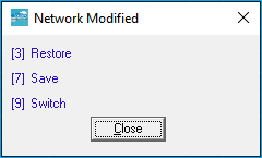
The NETWORK MODIFIED menu allows you to quickly 3 RESTORE, 7 SAVE, or 9 SWITCH modes.
Num Lock
Pressing the Num Lock key while in the Design Assistant will have no effect on the operation of the numbers on the numeric keypad. Therefore, the insert, delete, home, end, page up, page down, and arrow functions located on the numeric keypad itself will function only as numbers while in the Design Assistant.
Spec Editor
While in any Spec Editor, the Num Lock key behaves like a normal Num Lock key, that is, it turns On and Off the number lock on the numeric keypad.
Forward Slash
/ Like the NUM LOCK, this key has been remapped to function as a backspace key while in the ENTRY mode of The Design Assistant.
In the DESIGN mode, the / key toggles between standard display and expanded display.
When using the 0 ALTER command in the DESIGN mode, the / acts as a backspace where you can erase a keystroke or go back a column.
Star key
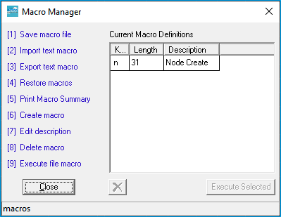
* Used to create or invoke user-defined command sequences called macros.
[ STAR ] [ STAR ] Opens the macro manager.
Enter
Enter ⏎ accepts keyboard input data and executes entered commands.
Enter Key
Not all Enter keys are marked "ENTER", some may be marked "RETURN" or may just have an arrow leading down, bending, and pointing to the left ⏎
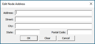
. Enter On the ftg | hc | cab | lv column, this opens the dialog to populate the address location.
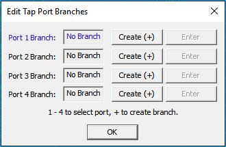
. Enter on a tap will open the EDIT TAP PORT BRANCHES dialog. Create and edit tap branches through this dialog.
Arrow Keys
Arrow Keys moves the cursor one field up, down, to the left, or to the right.
↑ Move up one node
↓ Move down one node
← Move left one column
→ Move right one column
Arrow Keys:
. ↑ or ↓ arrow will move the cursor to the top or bottom of the current branch.
. → or ← arrow will move the cursor to the branch beginning on the highlighted node.
Page Up
Page Up Moves back one branch.
. Page Up Move to branch 1
Page Down
Page Down Moves forward one branch.
. Page Down Move to the last branch of the network
Insert
Insert Inserts a line at the cursor position.
. Insert Inserts a line below the cursor position.
Delete
Delete Deletes a line at the cursor position.
. Delete Undeletes lines previously deleted with the Delete key.
Undelete
. DELETE Places the previously deleted nodes at the cursor position; so, if your cursor is not in the proper location the nodes will be replaced in the wrong location.
Scroll Lock
Scroll Lock Controls the Design Assistant scrolling mode.
Load Trunk Line
. - When invoked from a feeder leg, this command will load the trunk line to which the feeder leg is attached and place the cursor at the amplifier from which it originates.
Trun and Feeder
When using a trunk and feeder architecture where the trunk is the parent network and the feeder legs are children networks, remember not to place power supplies on the Appended versions of networks as they will be removed by the next Append. If you need to place supplies on networks that will be Appended (typically the feeder legs), place them within that network while it is the one currently loaded. Then save it and e-Append it before continuing. This is not normally a problem with today’s architectures because “feeder legs” are usually treated as branches rather than children networks, so there is no reason to append for powering purposes.
Quick Reference
↑ Move up one node
↓ Move down one node
← Move left one column
→ Move right one column
. ↑ Move to node 1 of the current branch
. ↓ Move to the end of the current branch
. ← Move into the left coupler branch column at this node
. → Move into the right coupler branch at this node
Page Down Move to the next branch number
Page Up Move to the previous branch number
. Page Down Move to the last branch of the network
. Page Up Move to branch 1
Home Move up one screen of nodes
End Move down one screen of nodes
Ins Insert empty node at cursor position
. ins Insert empty node below cursor position
Del Delete node at cursor position
. del Undelete node, placing previously deleted at cursor position
. - When invoked from a feeder leg, this command will load the trunk line to which the feeder leg is attached and place the cursor at the amplifier from which it originates.
+ Increment value
- Decrement value
Using the Mouse
The Design Assistant uses the mouse for various miscellaneous tasks. All actual design work, that is, design entry and optimization is done using the 10-key pad on the keyboard to maximize efficiency. The mouse is used primarily to access the pull-down menus, toolbar buttons, and to navigate the Design Assistant network. Mice equipped with a scroll wheel allow the user to scroll up and down through the nodes.
Left Click
A left mouse click on any of the pull-down menu commands or toolbars will execute that command.
A left mouse click on a single node (line) or piece of equipment within the Design Assistant will place the cursor at that location.
A double left click on a branch number (either the branch number or coupler ID will do) will move the cursor into that branch.
Right Click
A right click anywhere within the Design Assistant screen, excluding the window around the program, menu, toolbars, and scroll bars allows for customization of the display colors.
Networks
Depending on to whom you speak--a computer consultant, a cable systems engineer, or a psychologist, the term network can mean many things. Limiting the definition to our application, a network is a means of distributing signal, using "points" or "nodes". Signals travel along cables from point to point in two opposite directions. The signal can start from a headend, hub, or fiber receiver and travel towards the customer ("downstream", "forward path"). A signal can also originate from the customer or from a piece of equipment located on the network. The signal can travel towards the hub or headend by traveling along the return path. A network can be a plant extension, a feeder leg, a trunk run, or an entire fiber node consisting of up to 28000 branches and 128000 nodes (lines).
More About Nodes
To the Cable TV world, a node is known as a fiber receiver and the service area that it feeds. For Design Assistant purposes, we will define a node as a line of information in the Design, Entry, or Powering screens. In the real world outside the computer, it may represent a pole for aerial plant, or a pedestal for underground plant. Several nodes can represent a single pole or pedestal. One node in the computer can contain one active, up to four taps, two couplers (feeding up to two branches), a power supply, all ancillary equipment, and all the resultant signal levels and connectors. The backbone of the Design Assistant lies in accurately entering the information about each node into the computer. This information includes but is not limited to footages, house counts, equipment, etc.
Don't get locked into the idea that a single physical pole or pedestal must be represented by only one node. A “0” footage on a line represents an extension of the line above it and is therefore at the same physical location.
Node
Remember that it's helpful when starting out to think of a node as one line in the Design, Entry, or Powering displays.
Branches
A branch is a contiguous run of cable ending with a termination (branches should never end with couplers). Branch 1 usually starts at the headend or a fiber receiver. All branches after branch 1 start from a coupler (or possibly an internal coupler). A branch usually begins
where the strand or trench “breaks off” in a different direction, when a backfeed is created, or at multiple-output amplifiers. A branch may have any number of other branches leading off it. It is not necessary to begin a new branch when changing cable type, for example when transitioning from express to feeder. The Design Assistant clearly marks which nodes have branches and which do not. Moving from branch to branch is easy within the Design Assistant; also, finding a branch from any other branch in a network requires only a couple of keystrokes. It may be helpful when starting out to think of a branch as one page on the display that begins from a coupler.
Program limits
The Design Assistant can keep track of as many networks as your hard disk can store. However, the dimensions of each network do have some boundaries. A network cannot exceed 128000 nodes. A network cannot have any more than 28000 branches at a given time. Each branch requires at least 2 nodes worth of storage along with the number of nodes that the branch contains. Additionally, each trunk station with connected feeder legs takes an additional node worth of space, as does each multiple dwelling unit extension. Have your calculator handy? Putting it all together, with combined branches, nodes, and connected trunk stations, the equation looks like this:
(branches X 2) + total nodes + (connected trunk stations) + (multiple dwelling unit extensions) < 128000
In English, multiply the branches by 2, add the total number of nodes in the network, and add the number of connected trunk stations and multiple dwelling unit extensions. This number must be less than 128000. Now that we have explained all the limitations, please note that with today’s popular architectures, it is very unusual to reach the maximum branch or node limit.
File Naming Conventions
It's important to note how the Design Assistant names its files. Inside the Design Assistant, file names exist as 255 character lines of text. Each type of file has a unique file extension associated with it. While filenames can be as many as 255 characters, it is recommended that filenames be kept short yet descriptive.
It is typically recommended that all specification files in a project have the same name.
For example:
DENVER750R would be an appropriate name for the specs used for the Denver 750 MHz Rebuild project. If we were to create a new Actives spec file with this name, it would be written to disk as DENVER750R.ATV in the Spec file folder. The extension ATV denotes that this file is an Actives spec file. If we created a design network named DENVER001 (representing Node 001 of the project), it would be written to disk as DENVER001.NTW in the Networks folder.
Naming Specs
Naming all specification files with the same name simplifies the loading and copying of these files both within and external to the Design Assistant.
Here is a quick list of the files used by the Design Assistant.
filename.0AB- Macro file (system file)filename.PAR- Parameters filefilename.ATV- Actives filefilename.TAP- Taps filefilename.CPR- Couplers filefilename.CBL- Cables filefilename.PRC- Pricing filefilename.PER- Performance filefilename.NTW- Network filefilename.CNL- Control filefilename.BCK- Backup filefilename.MPN- Map number filefilename.MGD- Map Grid filefilename.DAP- Project Settings fileXspec.XPF- Xspec file fixed filenamefilename.F00- Custom form for comments –maximum of 8 characters
By default, the system files reside in the C:\Program Files\Lode Data Corporation\Design
Assistant\xx directory.
The remaining files are in the directories specified by the Project Settings. The procedure for changing these directories is outlined in the section Setting up the Project Settings earlier in this chapter.
XX
The XX in the file path above represents the version number of the program.
Exit the Program
To exit the program, press the X button at the upper right corner of the Design Assistant
window or go to the FILE → EXIT pull-down menu and press Exit. If you have not saved your work, the Design Assistant will display a dialog box asking if you would like to save your work before exiting the program. To save your work press YES, to discard any changes press NO, and to return to the program press CANCEL.