Menus & Toolbars
Pull-down Menus
The pull-down menus within the Design Assistant are used for various purposes. They are used to load files, unload files, change modes, access print functions, access specification file editors, and to access the help system, to name a few.
Pull-down menus and functions within them can be accessed by using a LEFT MOUSE CLICK or by holding down the ALT key and pressing the underlined letter at the same time (for instance ALT → F for the FILE pull-down).
File
The FILE pull-down menu is used primarily to create new files, load existing files, unload currently loaded files, print files, and save files. Some of the commands on the File pull-down menu cascade to display more options; these commands have an arrow to the right >.
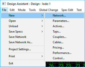
New
Most of the commands within the FILE pull-down are relatively self-explanatory. To start a new network file, hold the cursor over NEW and when the other options are displayed, simply click on NETWORK. The CREATE NETWORK dialog will open where you will place the name of the new network file.
The NEW NETWORK function will begin by prompting you for the name of the new network.
Once the new network name is entered, the KEEP EXISTING LEVELS box is displayed.
Pressing Yes to Keep Existing Levels retains all network specific tap output levels
defined in the current network. Next, it will automatically display the NETWORK
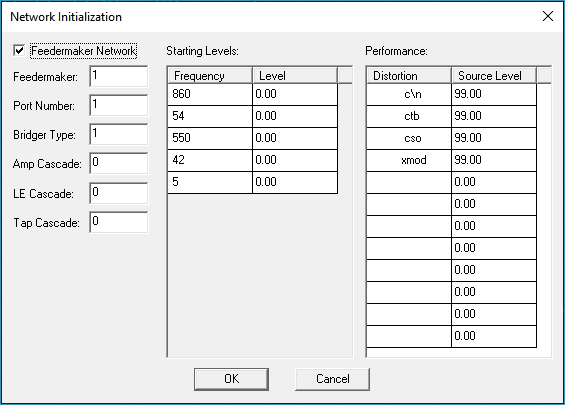
INITIALIZATION WINDOW to define the starting signal levels and characteristics of the new network. Upon clearing the Network Initialization Window, the Design Assistant will
automatically change to the ENTRY mode for immediate input of strand information. If
importing form the Drafting Assistant, you will switch to the DESIGN mode.
Creating a New Network

Levels and Network Init Window
More information and detail on LEVELS and the NETWORK INITIALIZATION WINDOW can be found in the Utilities section.
You can also create new Parameters, Actives, Taps, Couplers, Cables, Pricing, Performance, and Control files using the NEW menu. All perform in a similar manner opening a Create dialog box prompting you for the file name and location to save the file.
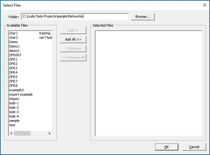
Open
To open an existing network file, hold the cursor over OPEN and when the other options are displayed, simply click on NETWORK.
You can similarly open Project, Parameters, Actives, Taps, Couplers, Cables, Pricing, Performance, Control, and Map Grid files.
Unload
The Unload function is used to unload individual specification files that are currently loaded. Typically, this is only used if a file is loaded and is not valid for the current project. For instance, it may be possible that one project would require a Performance file and the next project would not.
Save Specs
Save specification files as a new name or save to a previous version.
Save Network
Save a network file.
Save Network As
Save a network file with a new name or save to a previous version.
Project Settings
Open a Project Settings File (DAP).
Setting up a Project Setting File
See Getting Started - Project Settings on how to create a project file.
Print
The PRINT command will print any of the various items displayed: Specs, Networks, BOM, or MISC. Most PRINT report options are under the BOM or MISC menu.
More on Reports
Reports are described in detail in the Reports section.
Exit
Exit the program and close the Design Assistant. You may receive a warning prompt that your Project Setting file or Network has changed before exiting. Save the changes before exiting if desired.
Edit
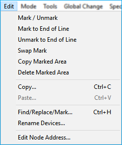
Mark/ Unmark
Toggle marking of node at the cursor position. This will place a blue line
just to the left of the NODE column. Marked areas may be copied, deleted, or BOMed separately.
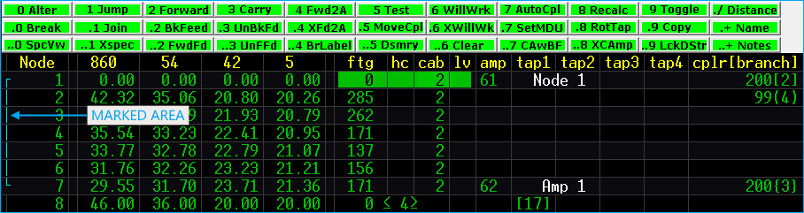
Marked Nodes
The example shows an area that is marked from Node 1 to Node 7. It is also possible that nodes in branch 2, 4 and 3 are marked as well if the MARK TO END OF LINE command was used from Node 1.
Mark to End of Line
Marks all nodes downstream of cursor to the end of line.
Unmark to End of Line
Unmarks all nodes downstream of cursor, to end of line.
Swap Mark
Inverts the selection by marking all nodes currently unmarked and unmarking all nodes currently marked.
Copy Marked Area
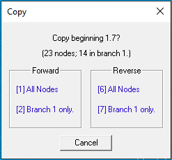 This allows marked areas in the current network to be duplicated and inserted at the cursor position in either forward or reverse format.
1 will copy all of the marked nodes and paste them starting at the cursor location.
2 will copy and paste only the marked nodes on Branch 1.
6 will copy all of the marked nodes and paste them at the cursor location in reverse order.
7 will copy and paste only the marked nodes on Branch 1.
Delete Marked Area
This command will delete only the marked nodes beginning with the node under the cursor and ending in each branch when an unmarked node is encountered. Branches that have all nodes marked will be deleted. Nodes upstream of the cursor and marked areas not contiguous with the marked area that includes the cursor will not be deleted.
Copy
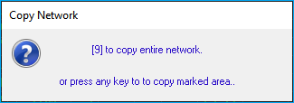
This command copies either the entire network or marked areas only. Selecting 9 will copy the entire network, any other key will copy the marked areas downstream from the cursor location.
Paste
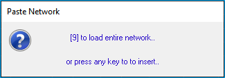
This command pastes the information copied using the copy command. The information is inserted at the cursor location. Selecting 9 will load the copied contents. It is almost always correct to select insert instead of loading, to permanently insert the data.
Copy/Paste
The COPY and PASTE commands are great for moving information between network files. Open two instances of the Design program and simply copy/paste.
Long time users often ask about our clip file. These functions completely replace the clip file and assoicated commands.
Find/Replace
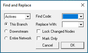
Find and replace Actives, Cables, Couplers, or Taps on the current branch, downstream from the cursor, or the entire network.

LOCK CHANGED NODES will allow you to lock all nodes where replacements have been made.
MARK ONLY will mark all nodes where replacements have been made.
Rename Devices
The Rename Devices command provides an easy way to change the names of Actives and Power Supplies on the current branch, downstream from the cursor, or the entire network.
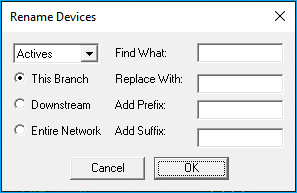
For example:
If your active names contain the name of the power supply in them and you wanted to change the Active name from N01P201 (where the P2 represents Power Supply 2) to N01PB01 (where PB represents Power Supply B).
Type P2 in the Find What: input area and PB in the Replace With: input area, select the option to cover the Entire Network and then click OK. Every active in the network that contained P2 will be changed to PB. You can also add Prefixes or Suffixes to the device names.
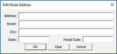
Edit Node Address
This command opens the dialog to populate the current locations address.
Mode
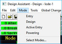
The mode pull-down menu can be used to switch the Design Assistant to DESIGN, ENTRY, ACTIVE ENTRY or POWERING mode. This pull-down is there mostly to aid new users; experienced users usually find it faster to change modes using the screen menu options.
For instance, pressing NUM LOCK 9 or ESC 9 from the DESIGN mode will switch to ACTIVE ENTRY. Pressing NUM LOCK 9 again will cycle to the next mode POWERING and so on.
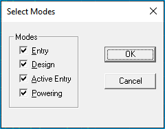
If you do not wish to toggle through all of the modes, use the SELECT MODE option. Checking
the mode name means the NUM LOCK 9 will toggle to that mode. Clearing the check mark indicates you do not wish to toggle to that particular mode.
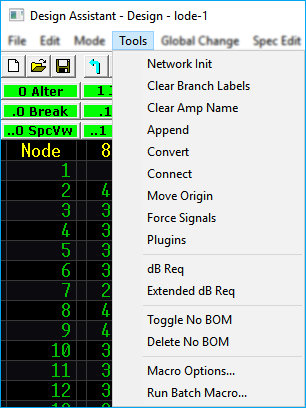
Tools
The Tools pull-down menu contains various commands for changing the status of the current network.
Network Initialization
Displays the Network Initialization Window.
More Info
For a complete description see the Utilities - Network Initialization Window section.
Clear Branch Labels
Removes any existing branch labels.
Clear Amp Names
Removes any existing amplifier labels. This includes other "active" devices. Active devices are indicated by a code placed the AMP column of The Design Assistant.
Append
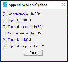
Attaches a network on disk to the network in memory, starting it as a branch beginning at the cursor location. The network may be appended without modification, clipped, or clipped and compressed. Clipping removes all nodes following the last active. If there are no actives in a network, nothing will be appended. Clip and compress removes the nodes after final actives and compresses multiple nodes into single nodes wherever possible. It is also possible to specify that the appended areas not be included in the Bill of Materials.
Legacy Command
Append is considered a legacy command and is not used in todays networks.
Convert
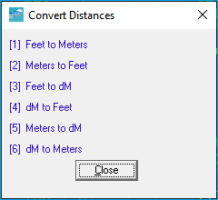
This function allows you to convert feet to meters, meters to feet, feet to decimeters, decimeters to feet, meters to decimeters, and decimeters to meters.
Conversion Warning
If you convert feet to meters and then convert meters back to feet again, you may not have the exact original footages due to differences in rounding.
Connect
Builds connections between the trunk network in memory and its attached feeder
legs. Connect should be used when feeder legs have been created with the New Network
option or when the name of the trunk network is changed. It is not necessary to use this
function if all feeder legs were created through the AMPLIFIER DEFINITION WINDOW.
Legacy Command
This is a legacy command. This command is only needed for legacy networks that utilize bridger and feedermaker devices.
Move origin
This command will rearrange the network so that the node at the cursor location will become node 1.1, turning around the nodes preceding it so that they are fed from that node. This allows you to select any point within the network as the point from which signal will originate. The nodes that had been upstream of the node selected will be converted into branch 1 and the downstream nodes will be moved onto branch 2 beginning at the new 1.1.
Advanced Command
This is considered an advanced command. New users may find it difficult when first using this command. It is recommended to save your network before using it so that you have a restore point.
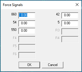
Force Signals
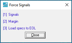
Sub functions:
[1] Signals: Forces the signals at the cursor position to user-specified values and recalculates signals from the cursor on. Forced signal levels will be reset by the next function that updates the signal levels at that node such as Test, any of the Forward Execution functions, RECALC, WILLWORK, etc., if done from a point upstream.
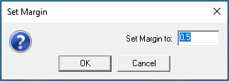
[2] Set Margin: Sets how far a tap has to be out of spec before being displayed red. If a tap is less than the margin value out of spec, it will be displayed in yellow. This function's setting does not override the TAP MARGIN setting in the PARAMETERS file; it will be retained only until a new PARAMETERS file is loaded or the same PARAMETERS file is reloaded.
[3] Specs to EOL: This function recalculates signals only from the cursor position onward. A network can only be saved with a single set of specs in place. Thus this is temporarily loading of specs for this single calculation.
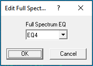
Plugins
Opens the Pad and Equalizer selector/editor for the amplifier or tap at the current cursor location.
Edit Amp
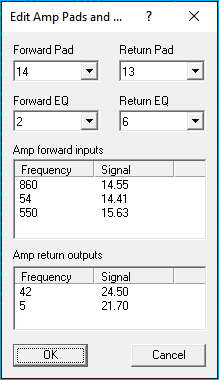
Edit Tap
Cursor Location
Your cursor must be on an amp or tap in order for the selector/editor to open.
More Info
See Design Mode Pad/EQ Selection for more details on how to use this command.
dB Req
Calculates the minimum signal requirements needed at the cursor to feed to the line extenders and ends of line downstream, whichever comes first.
Extended dB Req
Calculates similar to dB req with the addition of testing all available combinations of couplers to arrive at the minimum signal requirement.
Toggle No BOM
Toggles No BOM status of a branch on and off.
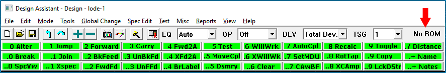
Turning No BOM on for a branch will cause it to be omitted from the Bill of Materials for the network. A branch not included in the Bill of Materials will be indicated by No BOM at the top of the screen.
Delete No BOM
This will delete all branches that have been marked to be excluded from the Bill of Materials.
Auto Appended legs
For legacy networks that use bridger and feedermaker devices, this will also delete all auto appended feeder legs as well as manually appended feeder legs that had been specified as not to be included in the BOM. This function will also delete auto appended legs whose corresponding trunk amps have been deleted.
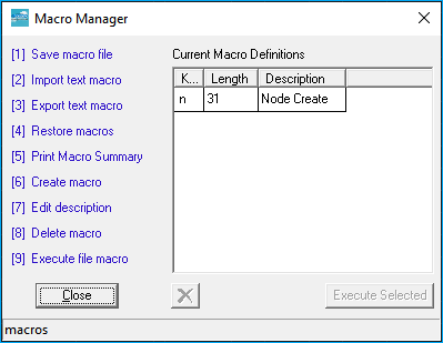
Macro Options
The Macro command allows you to record repetitive keystrokes that you can play back at any time. Due to the tremendous potential of Macros, we have dedicated an entire section to it.
More Info
See Macros for a complete overview of the Macro command.
Run Batch Macro
Run multiple macros on multiple networks.
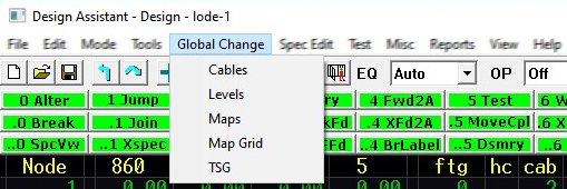
Global Change
Quickly change cables, levels, and maps in large portions of the network globally (all at once).
More Info
For a complete description of the Global Change menu see the Utilities.
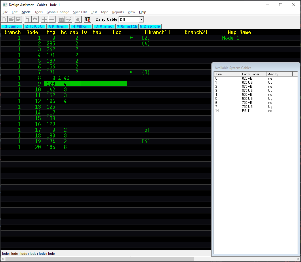
Cables
Set cable codes globally. This is useful for changing the cable types used in large portions of the network.
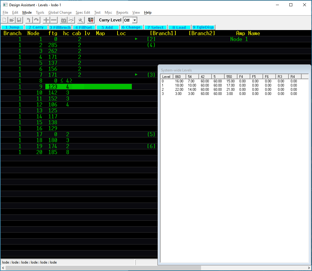
Levels
Set tap levels globally. Useful for changing the tap output/input levels used in large areas of the network and for adding new tap output/input levels to the network levels area.
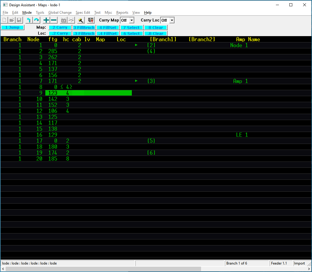
Maps
Allows you to change map and location numbers in large portions of the network.
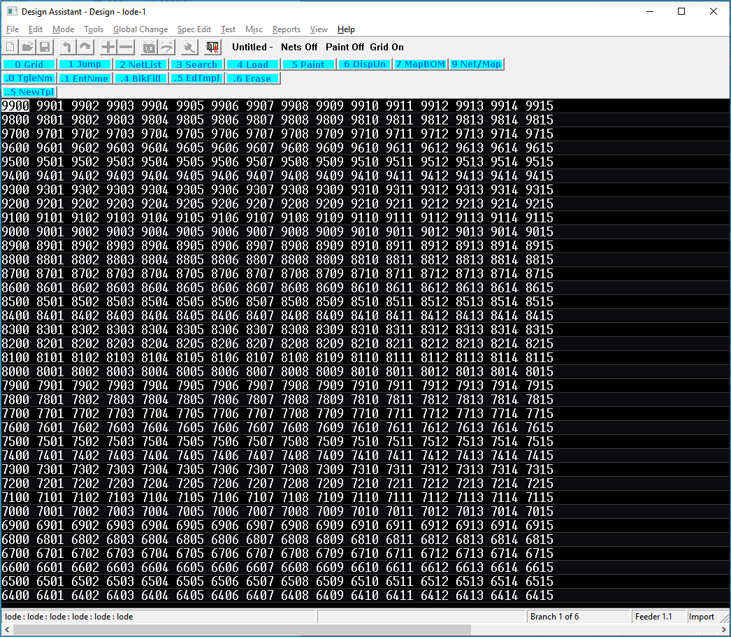
Map Grid
Shows maps occupied by the networks in the current network directory.
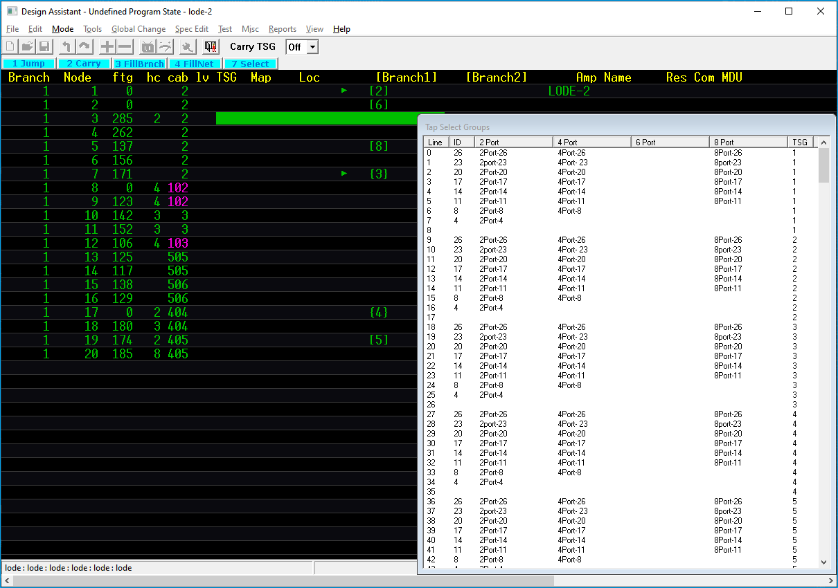
TSG
Globally change the TSG [Tap Selection Group] column.
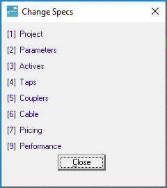
SpecEdit
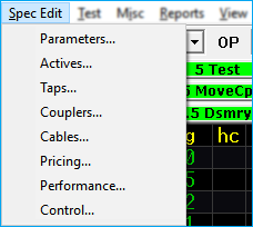
The SPEC EDIT pull-down accesses the editors used to create specifications files.
There are seven different types of specification files used by the Design Assistant:
- Parameters
- Taps
- Actives
- Couplers
- Cables
- Pricing
- Performance
Spec files are the backbone of The Design Assistant. In order for the program to calculate a network properly you must have a PARAMETERS, TAPS, ACTIVE, COUPLERS, and CABLES spec file. Each of the types are created and edited separately.
More Info
For a detailed description of the specification files, please refer to Building Specifications Files section.
You can also create a CONTROL file through the SPEC EDIT pull-down. A Control file is a group of network files that are added together. This provides the power to run a BILL OF MATERIALS (BOM) or an ACTIVE REPORT on multiple networks at the same time.
More Info
For more information on creating a Control file and its uses, refer to Reports.
Test
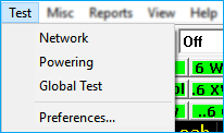
The test pull-down menu provides access to the various Design Assistant testing functions. These options include Network, Powering, Global Test, and Preferences.
Network
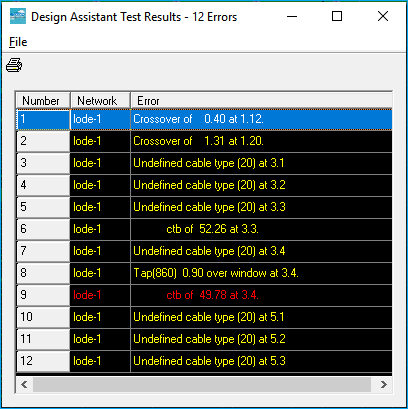
Tests the current network for signal, performance, and cascade errors. Double-click on any error to be taken directly to the error location in the network file.
Powering
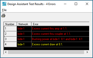
Tests the current network for voltage and current problems. Double-click on any error to be taken directly to the error location in the network file.
Global Test
Loads each specified network file in the specified directory and tests them.

Note
The test is run with the specs currently in memory.
Any unsaved changes to the current loaded network will be lost unless saved prior to running the test.
Preferences
Allows the user to turn off testing for certain types of errors. This is an option best left unexplored. It is possible to inadvertently turn off errors that are critical to design.
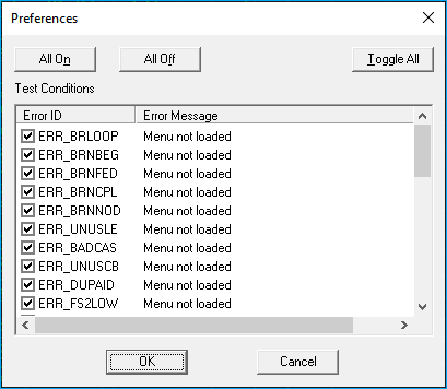
Do Not Turn Off
Do not turn off or otherwise mess with these setting unless you are fully aware of how they work. It's best to contact Lode Data Support before messing with these settings.
Misc
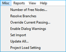
The MISC pull-down is used to access various miscellaneous commands that are used primarily for the maintenance of files, not production design.
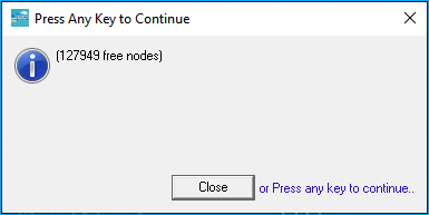
Number of Free Nodes
Displays the number of free nodes remaining in the current network.
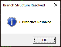
Resolve Branches
Function used to attempt to reconstruct a corrupt network. Network file corruption is extremely rare, so this function will probably never be needed.
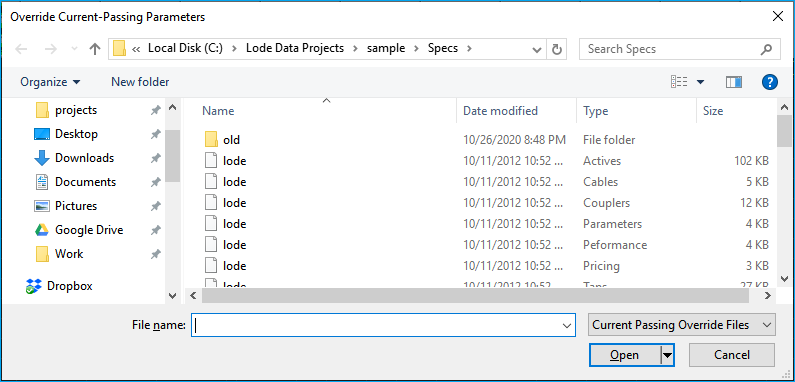
Override Current Passing
Loads a file used to override the current passing capabilities set within the Parameters file.
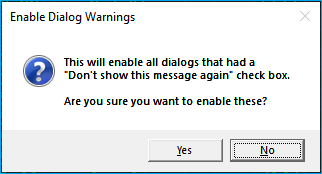
Enable Dialog Warnings
Resets the program to display all dialog-warning boxes that were previously disabled.
Set Import
If you have multiple Design Assistant programs open, select SET IMPORT to tell the Drafting Assistant which one you want to import from.
Update All
Update All opens each network in the network directory and saves it with the current specifications loaded.

Run before using control file
If you find your control file BOM or other control file reports are not correct then you should run an UPDATE ALL on all the networks in the reports. This will make sure all the networks in the control file are updated with the current specs.
Project Load Setting
This command allows you to select how your PROJECT SETTINGS are loaded and stored.
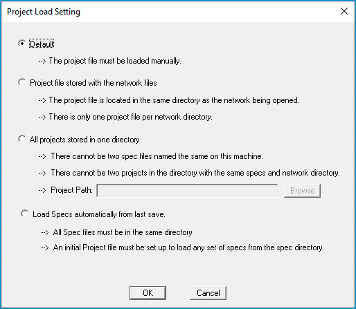
Four options are available:
-
Default: Project Settings are manually loaded upon starting the Design Assistant.
-
Project file stored with the network files: The Project Settings file is stored in the same directory as the network file that is being opened and only one Project Setting file is allowed in each network directory.
-
All Project files are stored in one directory: Select the Project Path by typing or browsing for the path. There cannot be two spec files named the same on the computer and there cannot be two projects in the directory with the same named specs and networks.
-
Load Specs automatically from last save: This option is used when all of your spec files for multiple systems are stored in one directory. After setting this option, create and save a project file for one of the sets of specs. Open a network that uses those specs. Opening networks that use different specs will automatically load the specification files.
Advance Setting
This is an advanced setting. Most users will only need the DEFAULT option.
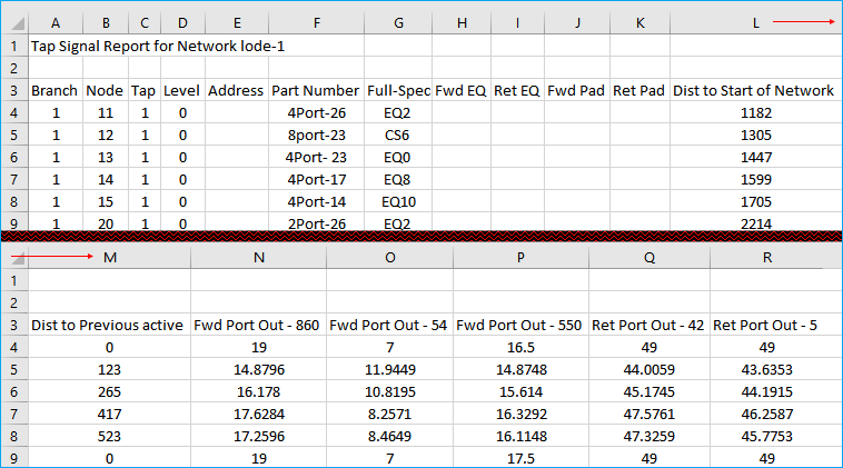
Reports
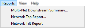
Multi-Net Downstream Summary
Creates an Excel spreadsheet that summarizes the number of homes, amplifiers, route, and cable for any number of networks.
Multi-Net information includes:
- [ A ] Network
- [ B ] Homes passed
- [ C ] Amplifiers
- [ D ] Line Extenders
- [ E ] Power Supplies
- [ F ] PCDs
- [ G ] Cable in feet
- [ H ] Strand in feet
- [ I ] Trench in feet
- [ J ] Total plant in feet
- [ K ] Cable in mileage
- [ L ] Strand in mileage
- [ M ] Trench in mileage
- [ N ] Total plant in mileage
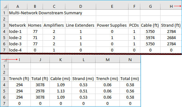
Network Tap Report
Creates a Excel spreadsheet of all the taps in the current network.
Tap information includes:
- [ A ] Branch
- [ B ] Node
- [ C ] Tap column
- [ D ] Level
- [ E ] Address
- [ F ] Part Number
- [ G ] Full Spectrum EQ value
- [ H-I ] FWD and RET EQ value
- [ J-K ] FWD and RET PAD value
- [ L ] Distance to start of network
- [ M ] Distance to previous active
- [ N-P ] FWD Port Outputs for all frequencies
- [ Q-R ] RET Port Outputs for all frequencies
Columns
Column letters may vary depending on how many frequencies you use in your specs. The sample shows 3 FWD and 2 RET frequencies.
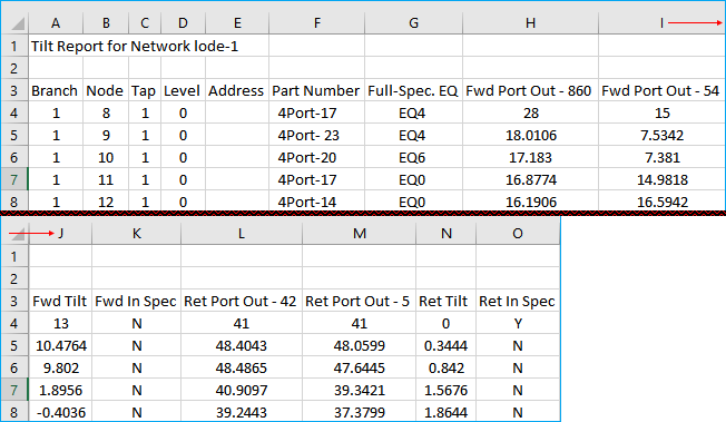
Network Tilt Report
The NETWORK TILT report is very similar to the NETWORK TAP report, however; This report includes the FWD TILT and RET TILT columns. It also includes FWD IN SPEC and RET IN SPEC columns so the user can quickly view weather the tap tilt is within the specified specifications.
- [ A ] Branch
- [ B ] Node
- [ C ] Tap column
- [ D ] Level
- [ E ] Address
- [ F ] Part Number
- [ G ] Full Spectrum EQ value
- [ H-I ] FWD Port Outputs
- [ J ] FWD Tilt
- [ K ] FWD tilt within spec [y/N]
- [ L-M ] RET Port Outputs
- [ N ] RET Tilt
- [ O ] RET tilt within spec [y/N]
View
VIEW contains a couple of commands to quickly change a couple of the view settings.
Show Grids
Toggles the grid display on and off.
Grid ON

Grid OFF
Show Tips
With this option turned on (default), an informational tip box relating to the location of your cursor will appear in the lower right corner of the Design Assistant window when in Design mode.
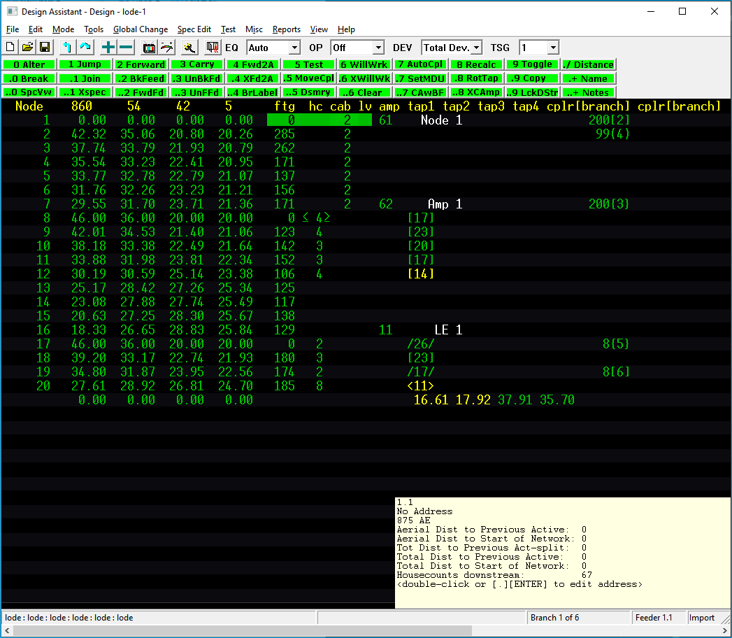
Cursor Locations:
-
Column -
FTG | HC | CAB | LV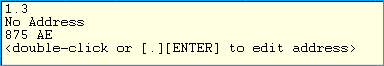
-
Branch.Node number
- Node Address
- Cable Type
-
Available commands
-
Column -
AMP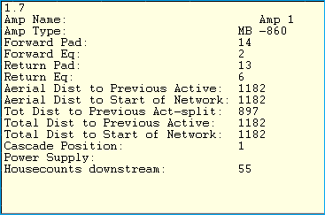
-
Branch.Node number
- Amp Name
- Amp Type
- Forward PAD
- Forward EQ
- Return PAD
- Return EQ
- Aerial Distance to Previous Active
- Aerial Distant to Start of Network
- Total Distance to Previous Active or Splitter
- Total Distance to Start of Network
- Cascade Position
- Power Supply
- House Counts downstream
Amp Info
Your cursor must be on an active device for the tip box to display.
-
Column -
TAP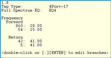
-
Branch.Node number
- Tap Type (part number)
- Full Spectrum EQ value
- Frequency header
- Forward frequencies
- FWD 1
- FWD 2
- Return frequencies
- RET 1
- RET 2
- Available commands
Tap Info and Line Numbers
Your cursor must be on a tap device for the tip box to display.
Tap line numbers may vary depending on the amount of FWD and RET frequencies you utilize in your spec files.
-
Column -
CPLR[BRANCH]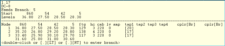
-
Branch.Node number
- Coupler value
- Feeds branch number (child branch number)
- Start Levels - these are the starting levels of the coupler leg (child branch) at the given frequencies
- Preview of coupler leg (child branch)
- Available commands
Child Branch
The child branch is the coupler leg. This could be the other leg of a 2 or 3 way splitter. If a directional coupler is used, this is commonly the high loss leg.
TIPS OFF
Help
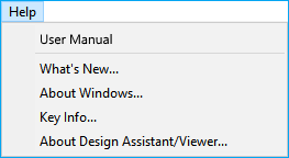
The Design Assistant HELP menu contains a link to our online User Manual.
The HELP pull-down includes four more options:
- What’s New
Displays the What’s New file detailing new features and maintenance in the current version.
- About Windows
Displays the Windows version and registration information.
-
Key Info
Key Info displays information about the security key installed on the machine
including the serial number, products it will run, key date, as well as timer key expiration date.
- About Design Assistant
Display the Design Assistant version information.
About Key Info
More information about our hardware locks/USB keys can be found on our FAQ - USB Keys section
Toolbars
In addition to the pull-down menus, the Design Assistant also makes use of toolbars that give one-click access to a few Design Assistant commands.
Toolbar

 New Network
Starts a new network. Same as selecting FILE → NEW → NETWORK from the pull-down menu.
 Open Network
Opens an existing network. Same as selecting FILE → OPEN → NETWORK from the pull-down menu.
 Save Network
Saves the current network. Same as selecting FILE → SAVE NETWORK from the pull-down menu or pressing ESC/NUM LOCK 7
 Jump to Parent Branch
If on a branch other than branch one, it will move the cursor to the starting location of the current branch.
 Jump
Jump
Displays a limited jump dialog to jump to different branches.
 Increment Entry
If placed over an existing piece of equipment, it will change the device to the next higher line number designated in the specification file. If placed in an empty column, pressing the [ + ] button will place the first device found in the specification file.
 Decrement Entry
If placed over an existing piece of equipment, it will change the device to the previous line number designated in the specification file. If placed in an empty column, pressing the [ - ] button will place the first device found in the specification file.
 Test Network
Tests the current network for signal, performance, and cascade errors.
 Test Powering
Tests the current network for powering problems.
 Edit Plugins
Opens the Pad and Equalizer selector/editor for the amplifier or tap at the current cursor location.
More on Edit Plugins
See Design Mode Pad/EQ Selection for more details on how to use this command.
 Escape Functions
Escape key and Network Modification Window.
 Default EQ Placement
Quickly change the default EQ placement Parameter setting.
 Default Tap Optimization
Quickly change the default tap optimization Parameter setting.
Parameters Settings
More information on the default EQ and Tap Optimization settings can be found in the Spec Files - Parameters section
 Total Tap Deviation
Set the total tap deviation (DEV) to be used.
More on Tap Deviation
More information on the Tap Deviation pulldown can be found in Chapter 7 Design Menu (page 61 / 71 of PDF).
 Tap Selection Group
More on Tap Selection Group
More information on the Tap Selection Group (TSG) can be found in Taps
Numbered toolbars
The numbered toolbar commands change depending on which mode you are in. Thus, these toolbars will be covered in their specific MODES. Use the links below to jump directly to the mode.


