Parameters
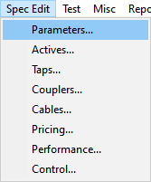
Select the Parameters option from the Spec Edit pull-down to display the current Parameters spec file. The current parameters file defined in the Project Settings will open. The file name and location are displayed at the top in the title bar of the window.
The Parameters file contains six separate pages or tabs of general information such as maximum crossover, maximum tap outputs, pedestal sizing, and power supply information.
General Parameters
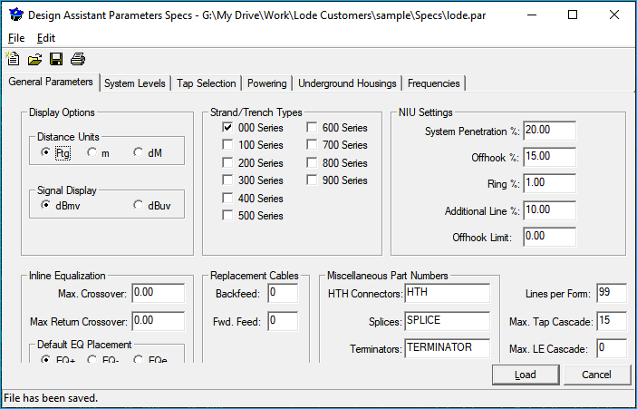
Display Options
Distance Units: This indicates whether the units of distance are in feet, meters, or decimeters. This only affects the display and does not modify previously entered specs. For example, entering cable attenuation in feet and then changing this field to meters will not automatically update the cable attenuation or the distances already entered into existing networks.
The default is feet.
Signal Display: This indicates whether the signal levels are displayed in dBmv or dBμv. The only effect of this is a change in display format to accommodate more digits before the decimal point for dBμv, it will not automatically update the values in the spec files.
Inline Equalization
Default EQ placement: This specifies when in-line equalizers will be placed in the Design when performing any automated tap placement routines like forward to le or WillWork. If it is set to EQ+, they will be placed when the maximum crossover specification has been exceeded. If this is set to EQ-, automatic equalizer placement will be off, this means in-line equalizers will not be selected automatically. If it is set to EQe, equalizers will be placed when the maximum crossover specification has been exceeded except at the last node of the branch or in the node immediately preceding an active. The current EQ setting is displayed to the right of the toolbar in the Design menu.
Maximum crossover: Maximum crossover refers to the maximum that the forward low signal may exceed the forward high signal before an in-line equalizer is placed. This is measured at the tap spigot and will not cause the automatic placement of an in-line equalizer at a pole without taps. Typical values for the maximum crossover range are from zero to 3 dB.
Maximum Rtn Crossover: This checks for crossover on the return path. Set this value to 99 if you do not care about crossover on the return path. The forward path crossover is used to automatically place in-line equalizers; the return path crossover, if used, will not automatically place in-line equalizers. It will only identify an error when it occurs by turning the tap yellow. You then have the option to place an in-line equalizer manually.
Strand/Trench Types
Strand/trench types: This allows you to specify which cable categories you wish to include in linear strand/trench calculations to get an accurate cable bearing strand distance on your Bill of Materials. To use this feature, simply check the box next to the cable series that you wish to include in your mileage count. Note that if this is not set up correctly, the figures in the Downstream Summary for strand, trench, and total may not be correct. The Downstream Summary is .4 Dsummary in the Design menu.
Cable Series
See Cables for more information on the cable series. Understanding cable series is extremely important to ensure you correctly code cables for reporting purposes.
Misc
Lines per form: For all Design Assistant print functions, this value specifies the number of lines that can be physically printed per page. Paper that is 11 inches long can print 66 lines. Setting this value to 60 will print only 60 lines per page, leaving three lines at the top of the page for a top margin, and three lines at the bottom of the page for a bottom margin (three lines are equal to ½"). If Lines per formis set to0, no form feeds will be sent (recommended for most printers).
Allow Over Equalization: A check mark in this box instructs the Design Assistant to select equalizers for taps and actives that have the best fit, that is it will select the equalizers that come the closest to the desired slope even if it creates an over-equalized situation. Normally (no check in this box), the Design Assistant will never select equalizers that over-equalize.
Replacement Cables
Backfeed: This allows you to specify a different physical cable as a backfeed replacement cable type. For every span that is backfed, the Design Assistant will replace the cable on the input to the amplifier with the cable type specified here.
Fwd. Feed: Forward feed, the same as backfeed replacement cable, but used for forward feeds.
Usage
This feature is not normally used in a new-build situation, but it can be very helpful in re-build projects requiring the use of existing cables. For most projects these will be set to 0 which will not replace any cables.
NIU Settings
NIU Penetration (%): Represents the expected Network Interface Unit penetration percentage for power consumption analysis in Telephony designs. This power consumption analysis is performed by the NIUtest command, .8 in the Powering mode. The number entered here represents the percentage of house counts to actually use the default NIU array. The default NIU array is entered and defined on the first line on the NIU Arrays tab in the Couplers file. Note that this penetration percentage is used only at house counts without additional MDU window information. Explicit placement of NIU arrays within an MDU window will override any power estimates based on this figure. If this penetration percentage is set to 50%, then half of the house counts listed in the hc column in the Design mode will be assumed to have the default NIU array for powering calculations. The NIU Penetration % will determine how many default NIU arrays are calculated into the Bill of Materials.
off-hook%: Represents the amount of time that any given phone line is expected to be off-hook or active. This number includes only expected off-hook time, not ring time.
ring %: Represents the percentage of time that any given phone line is expected to actually be ringing.
addl. line %: Represents the percentage of available additional lines in a given NIU array that are not initially active but can be expected to be assigned for hook-up in the future. For example, assume an NIU array has a total of ten possible phone lines available and originally has four active lines leaving six available additional lines. The additional line % is the percent of probability that each of the remaining six lines will be assigned for hook-up. An additional line percentage of 50% in this case would mean that half of the remaining lines (three) are actually expected to be assigned (for a total of seven) at a later date.
off-hook limit: The maximum number of lines your telephony receiving/switching equipment can activate at one time in your typical powering area. This setting is used to check for call-blocking in the NIU Statistical analysis, .8 NIUtest from the Powering menu. It will supersede any off-hook setting made in the NIU worst-case test. Setting the off-hook limit to 0 will disable the call-blocking test.
Maximum LE cascade: Specifies the maximum number of line extenders that may be placed in series. Note that this has no bearing on the number of line extenders that may be used in a network. There are only three valid values for this field: 1, 2, and 3.
Custom Cascade
The custom cascading feature found on Page 3 of the Actives file will override any settings here, but if you choose, you may follow the Design Assistant's built-in LE cascade checking
LE Cascade Checking
To use the Design Assistant's built-in LE cascade feature, your line extenders should be defined on the first few lines in the Actives file as Active ID's 11, 21, 22, 31, 32, and 33. The placement of an 11 LE represents 1 LE in cascade, first LE. 21 represents 2 in cascade first LE. 22 represents 2 in cascade second LE. 31, 32, 33 represent 3 in cascade first, second, and third, respectively.
Therefore, a value of 1 in the Max LE Cascade field will allow only the placement of an 11 LE without a resultant error message. A value of 2 would allow placement of an 11 or a 21 and 22 (in cascade) without a resultant error message. A value of 3 would allow the placement of an 11, a 21 and 22 (in cascade), or a 31, 32, and 33 (in cascade).
Cascade Violations
If the cascade is violated, the Design Assistant will not hamper your ability to place the line extender, it will simply produce an error message during a network test.
Maximum Tap Cascade: Sets a maximum number of taps that can be placed in cascade. If this cascade is exceeded, the Design Assistant will produce an error when the network is tested.
Error
The error only lists the first tap that is out of cascade in any given line. For example, if the max tap cascade was set to 10 and there were 14 taps in cascade, only the 11thtap will have an associated error.
Miscellaneous part numbers
HTH: Part number for housing-to-housing connectors. They are automatically added to the Bill of Materials any time two or more pieces of equipment reside on one line or multiple lines separated by a 0 footage within the Design Assistant. The only exception is if a coupler has been specified as internal no housing-to-housing will be BOMed.
Splice: Part number for a splice block. A splice block, as opposed to a straight splice, requires two cable connectors also to be used. A splice is automatically selected every time cable types change with no physical device in line.
Terminator: Part number for terminators (housing terminator only). They are automatically selected any time there is a non self-terminating device on the last node in a branch and anytime a coupler creates a branch but there is no equipment on that branch.
System Levels
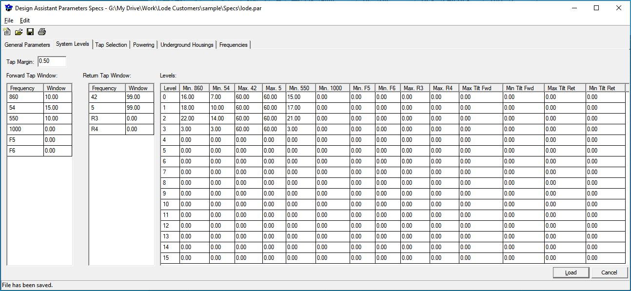
The System Levels tab of the Parameters file covers system-wide output/input levels. Typically, these are used primarily for tap output levels, but they may be used anytime a minimum signal level is desired (for instance, at an MDU location or at a future split point).
Levels: The minimum system levels ID are numbered 0 through 15 in the level column. These numbers are used in the lv field of the ftg | hc | cab | lv columns of the Design mode. A 0 is the default entry for the lv field, so the most commonly used set of levels should be placed there and it is generally reserved for the default tap output spec.
These 16 levels may represent typical long drop levels, short drop levels, levels at the converter (for use with the MDU window functions), levels needed for future splits, or any other desired levels. Any network that uses this Parameters file will use these 16 sets of levels.
You may also set up network specific levels. These levels would be numbered 16 through 31, and can only be viewed or modified while in the Entry menu, of the network containing these specific levels.
Utilities Levels
For more information see Utilities ➡ Levels.
Min/Max Signals: The min signal columns specify the minimum forward output levels. The columns are labeled (by default) high, low, F3, F4, F5, and F6. The column headings can be customized in the Frequencies page of the Parameters. The Max Signals represent the maximum return input levels. These column headings are labeled (by default) Rh, Rl, R3, and R4 and also may be customized on the Frequencies page.
Note: Both forward and return levels are used to select taps. Therefore, setting the Maximum Return levels on this page too low will force the automatic and semiautomatic tap selection routines to select lower tap values, to stay below the maximum return level. This may result in forward levels much higher than desired at some tap spigots. If the taps you're using have no specific Maximum Level spec, and you are not limited by low-return-output converters being used in your system, you should probably set the Maximum Return levels to 99.Even if the design you are doing is completely unconcerned with return levels, do not simply set the rh and rl figures to 0! If you do, no taps will be selected, since you are telling the program that 0 dB is the highest level allowed back through the tap.
Tap Selection Frequencies
It is possible to specify which two forward and which two return frequencies are used for tap selection on the tap selection page.
Tap margin: The number of dB that the output of a tap may drop below the minimum tap output. Or the amount that the return input to a tap can rise above the maximum before it is flagged as red in the Design screen. Taps that are out of spec by less than the tap margin will be displayed in yellow. The Design Assistant will not auto-select any taps that fall in the marginal area; they must be forced in at the designer's discretion. Typical values range from .5 to 1 dB, though it may be set to any desired value, according to your design tolerance.
Tap window: Permits setting a maximum forward and minimum return level at all tap spigots. Enter figures for the forward tap window here if a design calls for its tap ports to carry no more than a certain maximum output. These values represent that maximum output when added to the Minimum Signals figure for a given node. For example, if you have a minimum tap output specification of 16 dB (Forward high), and are not allowed to exceed 26 dB from that tap port, enter a 10.00 for the tap window. Taps with an output higher than that limit is flagged as an error in the test function and is displayed in yellow. Should a design call for a certain minimum return level at the tap spigots, first determine a typical tap's maximum return through-put (probably from line 0). Next, enter Tap window Rh and Rl figures for subtraction from that maximum which will bring you to your desired minimum return level for TestWindow to check. If you are not concerned about a maximum tap output, disable TestWindow, by placing 99 in each of these four lines. Typical values for tap window are range from 99 to disable it all the way down to 4 or 5.
Tap Selection
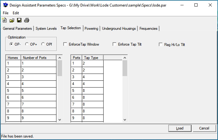
Optimization: Used to specify the default tap optimization setting within the Design mode. Tap optimization is usually set either to OP- or OPf because the use of tap optimization can sometimes call for the use of odd combinations of taps where they may not actually be needed.
OP-turns off tap optimization so all taps are selected using only the criteria set up on this page and the system levels page.OP+turns on tap optimization so that the Design Assistant will select the tap or combination of taps with the lowest insertion loss. For instance, there may be times when a 2 port tap and a 4 port tap would have a combined insertion loss lower than that of an 8 port tap. With tap optimization off, the Design Assistant will select the 8 port tap, but in this case, with tap optimization on, the Design Assistant will select the two taps.OPfstands for tap optimization on failure. In the previous example, withOPfturned on, the Design Assistant will select the 8 port tap if there is still enough signal available to feed on downstream, but pick the 2 port and 4 port if there is not enough signal available to feed downstream.
Enforce Tap Window: It forces all tap forward outputs and return inputs to fall within the range established by the Tap window and System level settings. This option is used primarily when using taps with plug-in pads and equalizers.
Homes | Number of Ports | Ports | Tap Type: On the left side of the box are three separate edit boxes. The first two are labeled as Homes and Number of Ports. These are used to specify how many tap ports are needed to feed a certain house count. Typically, you need 1 port for 1 house count, 2 ports for a 2 house count, and so on, but this provides the flexibility to tap for more or less than 100% of the homes.
The third edit box is labeled Ports and Tap type. This box tells the Design Assistant what tap type (2 port, 4 port, or 8 port) to select based upon the number of ports required to feed the house count.
Powering
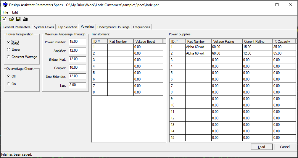
Here you may define up to 15 different types of power supplies. On the left portion of the screen, enter the power supply part number, the voltage and current ratings, and the % of the maximum current capacity for the power supply. When entering a power supply in the Powering menu, use the ID# shown on the far left.
Power interpolation: If set to step, power interpolation is turned off and powering calculations for the active devices will be based solely on the stair steps entered on the Powering Data page of the Actives file. If set to Linear, power interpolation is turned on to perform the calculations for the active devices on a linear basis. The Design Assistant will interpolate the actual current draws for the active devices at the true voltage thereby eliminating the jumps that occur in the stair step method. If set to Constant Wattage, power interpolation is turned on to perform modeling of constant-wattage devices. Here, the current draw changes across each voltage range will vary slightly from linear to maintain constant wattage.
Overvoltage Check: If set, this checks for equipment that may be specified at a operating voltage less than that of the power supply voltage. For example, a 60V (maximum) device within a 90V power supply area.
Max Amperage through...: Indicates the maximum number of amperes that each piece of equipment can pass for powering. If the Max A number is exceeded, the offending device will be flagged in red, also, the 5 Test and [.6] TestArea functions in powering will alert you if there are any problems. Bridger allows the Test functions to check for excess current levels at a parent network's connection to its offspring networks. Some common values include: 15 for Inserter, 10 for Amp, 10 for Bridger port, 10 for Coupler, 10 for Line Extender, and 6 for Tap. These numbers will vary for each manufacturer and each piece of equipment so is sure to double check. If this value is left at 0, all equipment will be flagged red when a power supply is entered.
Transformers: Provides a voltage boost downstream of transformer placement.
Underground Housings
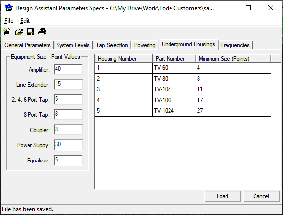
This page is used to specify how the Design Assistant selects underground housings for the Bill of Materials. At each underground location the Design Assistant will add up all the equipment located there and consult this page to determine the correct size housing.
U/G Housing #1-#5: The Design Assistant supports five different sizes of enclosures. Enter the part numbers of those housings here. Please note: housing #1 should represent the smallest available pedestal progressing to #5, which should represent the largest.
Min size: Min size sets the minimum point total for each particular type of pedestal to be BOMed. At each underground location, the Design Assistant will select a pedestal with the minimum size closest to the total points allocated without exceeding it. If a pedestal is selected based upon the point total for Min size #1, U/G housing #1 will be BOMed; Min size #2 will BOM U/G housing #2, and so forth.
Equipment size - point values: Point values and Min size work together to BOM the correct size pedestal according to the amount and type of equipment at each pedestal location. In the point value column, enter a number to represent the size of each physical device. The lowest point values should correspond to the smallest physical devices and increase as the equipment gets larger. The Design Assistant will total the points at each underground node, identified by an odd numbered cable type, and match them to the minimum size requirements which then refer to the U/G housing column to BOM the correct size pedestal.
Example
Assume a Min size #1 of 5, Min size #2 of 10, and Min size #3 of 15.
A point total of 3 would not BOM any pedestal because it is under the minimum size requirement of 5 points for Min size #1.
A point total of 9 would BOM an U/G housing #1 because 9 falls between Min size #1 and #2.
A point total of 15 would BOM an U/G housing #3 because 15 is the Min size #3.
For a much more detailed example of point requirements and minimum size settings, please seeAppendix A: Miscellaneous,sectionPed Counting.
Frequencies
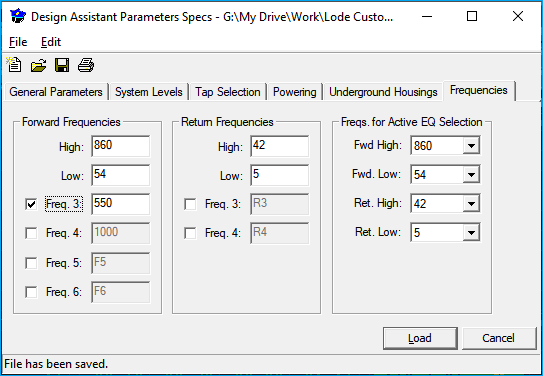
The frequencies page of the Parameters allows for customization of frequency headings and it is here that extra forward and return frequencies are enabled.
Forward / Return Frequencies: To customize a frequency heading, simply enter the desired frequency - for instance, 860 or 860 MHz. The default headings are high and low for the forward and RH (42) and RL (5) for the return. Once a heading has been entered here, the new name will be reflected in all Design Assistant screens.
Two forward and two return frequencies are required for the Design Assistant to select forward and return equalizer values correctly (it is not necessary, however, to design two-way systems). To enable extra forward and return frequencies just check the boxes next to the desired number of extra frequencies.
Freqs. for Active EQ Selection: These options are used to specify which two forward and two return frequencies will be used to select pads and equalizers. It is possible to choose from any frequencies that are enabled on the Frequencies page.