Performance File
Select Performance... from the Spec Edit pull-down to display the current Performance spec file.
Create Performance File
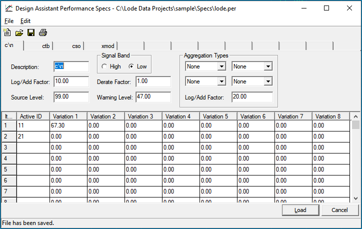
When creating a new Performance file, you will be presented with a clean slate. That is, the Performance file will be completely blank. There will be 12 blank tabs that will access 12 empty pages. When a distortion type is defined on a blank page, the tab used to access that page will be titled the same as the description entered for that distortion type. In the screen shot above you will notice there has been four distortion types defined: c\n, ctb, cso, xmod.
Description: 14 character alphanumeric description.
Signal Band: The frequency at which that particular distortion type will be tracked - the forward high, or forward low.
Log\Add factor: The logarithmic equation at which that particular distortion type is calculated. The addition factor for carrier to noise is 10 because it is calculated using a 10 log rule. The addition factor for composite triple beat is 20 because it is calculated using a 20 log rule, and so forth. This field is not limited to just a 10 or 20, but the number entered here must be a positive number.
Derate factor: The amount of degradation that occurs with a 1 dB change in signal level. A positive number entered here will cause the Design Assistant to key off the input level for that particular distortion type, whereas, a negative number will cause the Design Assistant to key off the output level. For example, carrier to noise gets 1 dB worse for every 1 dB decrease in input level. Therefore, you would enter a positive 1 here for carrier to noise. Composite triple beat gets 2 dB worse for every 1 dB increase in output level. Therefore, you would enter a negative 2 for composite triple beat.
Source Level: The level of the distortion before any equipment is placed. The source level could refer to the level at the headend or hub, or at the fiber receiver. It is the most common for the source level to refer to the level after the headend and fiber link but before the fiber node. This level is typically not found in manufacturer specification catalogs. You will probably have to get this from the cable system itself. Note that this should always be a positive number for all distortion types. Higher source level values will have less effect on the calculations. Therefore, if you are not able to find a valid source level, you may set it to 99 and the source level will have a negligible effect on the calculations. To turn off the performance calculations for a particular distortion type, set the source level for that distortion to zero.
Warning Level: The level at which the Design Assistant will flag (in yellow or red) a certain value. The flag will be in yellow up to 3 dB below the warning level and then turn red when it is more than 3 dB below the warning level. This number should always be input as a positive value. To disable the error messages you may set the warning level to zero.
The remainder of the page is used for entering the "single unit base distortion levels" for the distortion type described on the same page. There are 12 separate pages, one for each distortion type. The levels that need be entered in the Actives Variations here is the amount of distortion contributed by one amplifier.
For example, the formula to calculate the "single unit base distortion level" of carrier-to- noise for an amplifier that has an input of 11 and a noise figure of 9 (from the manufacturer's specs) is:
C/N[1] = 59 + input - noise figure

= 59 + 11 - 9

= 61
Therefore, a 61 would be entered here for that particular amp.
The different columns, labeled #1 through #8, refer to the configuration table page of the Actives file. If you recall, the configuration table (of the Actives file) allows for the custom configuration of amplifiers. You can configure amplifiers with plug-ins and also specify new ID#s for the eight different custom configurations possible using each base unit amplifier. For example, assume you had specified that an 11 is a base unit line extender. An 11a, therefore, could be the 11 code line extender with one plug-in, an 11b has two plug-ins, and an 11c has three plug-ins. Then, you would need to input the base unit distortion for the 11 in column #1, the 11a in column #2, the 11b in column #3, and the 11c in column #4. If you have not added any custom configured amplifiers then you will only need values in column #1 on these pages.
To view the performance calculations, you will need to be in the Design menu, then press 9 Toggle and 0 for Signal Display. Note that only the first five characters of this description will be displayed while viewing the performance calculations in the Design mode.
For your reference, the following is a list of basic distortion formulas. These formulas express distortion as a positive ratio of desired signal to undesired signal. If a manufacturer provides negative numbers for the different distortion types, drop the minus sign for use here.
Carrier-to-noise (C/N)
Carrier-to-noise (C/N)C/N for a single amplifier:
C/N[1] = 59 + input level - noise figure
C/N for a cascade of k identical amplifiers:
C/N[k] = C/N[1] - 10 log(k)
Cross Modulation (X-Mod)
X-Mod for a single amplifier:
X-Mod[1] = (X-Mod spec*) + 2(rated output* - actual output)
X-Mod for a cascade of k amplifiers:
X-Mod[k] = X-Mod - 20 log(k)
Second Order Distortion (SOD)
SOD for a single amplifier:
SOD[1] = (SOD spec*) + (rated output* - actual output)
SOD for a cascade of k amplifiers:
SOD[k] = SOD[1] - 10 log(k)
Composite Triple Beat (CTB)
CTB for a single amplifier:
CTB[1] = CTB spec* + 2(rated output* - actual output)
CTB for a cascade of k amplifiers:
CTB[k] = CTB[1] - 20 log(k)
* Represents the manufacturer's rated levels.
To help you insert a meaningful warning level, here are the Federal Communications Commission (FCC) standards as of July 1, 1995:
- Carrier-to-noise 43
- Carrier-to-Cross Modulation 51
- Carrier-to-Discrete Second Order 51
- Carrier-to-Composite Second Order 51
- Carrier-to-Discrete Third Order 51
Carrier-to-Composite Triple Beat
- Standard 51
- IRC 47
- HRC 47
It is recommended that you acquire the most recent FCC guidelines for accuracy.