Powering Mode
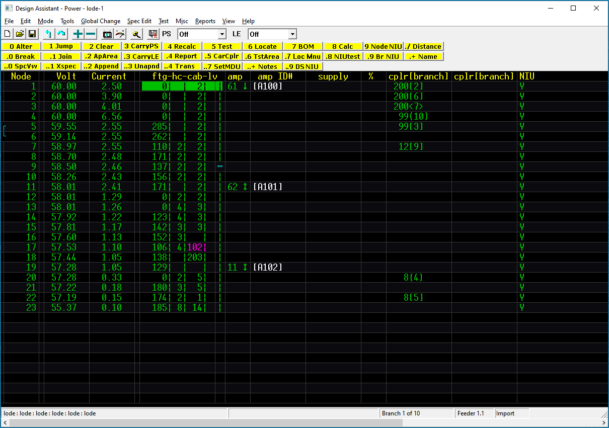
The Powering display is very similar to the Design screen display except that instead of signal levels, voltage and current levels are displayed. The display also allows the placement of power stops and power supplies. Power Mode (shown below), is an example of a very small network displayed in Powering.
Above the toolbar are the menu pull down options. These are covered else where and are static across modes, though some menus are disabled in certain modes.
Toolbar Buttons

📄 New Network
📂 Open Network
💾 Save Network
↰ Jump to Parent
↷ Jump to
➕ Increment
➖ Decrement
📺 Test
 Test Power
🔌 Edit Plugins
 Escape
PS OFF | ON
Carry Power Supply: Denoted by PS. When ON, this indicates that the cursor is either carrying a power supply or if no actual power supply is present the cursor simulates a power supply.
LE OFF | ON
Carry Line Extender: Denoted by LE. When ON, this indicates that the cursor is carrying an amplifier.
Power Commands Toolbar
The next three lines of the menu display the functions accessible from here and what key to use to invoke them.

At the bottom of the screen, the specification files that are currently loaded, the current branch number, the feedermaker indication, and import are displayed.

Columns
The remainder of this screen is separated into the following thirteen columns:
Node
Displays the node (row) number. It is useful for jumping to specific locations in the network.
volt
Displays the voltage at this location. The voltage displayed here is the voltage level after the footage specified on the same line.
current
Displays the current (amperage) requirements at that location.
ftg
The distance, usually between poles or pedestals.
hc
Number of units to feed from that span location.
cab
Cable ID value from the cable spec file.
lv
Tap port level defined in the parameters spec file.
FTG | HC | CAB | LV
Although these values are usually entered in the Entry mode, you may edit them or add new ones from within the Design and Power mode using 0 ALTER
=
Represents the presence of a power stop. Located on the separator character between the lv and amp columns.
How to place a power stop
See Placing Power Stops in the next section of this chapter.
amp
This is the amplifier column for any amplifier defined in the spec files. In-line equalizers or any of the Q values.
Building Spec Files
See Building Specification Files, section Create Actives File: Bridgers\Feedermakers\Inline Eqs) are also placed in this column.
amp ID#
Displays the label of any active device at that location if one exists and has been named.
supply %
Displays the type, label and percentage of operating capacity of a power supply at that location if one exists.
cplr [branch]
These columns are for couplers and branch numbers. The number within the brackets is the number of the branch that begins at that node. A number directly to the left of the [branch] represents the coupler ID number. A dash “- [branch]” indicates that there is a branch originating at this location but a coupler type has not yet been specified.
NIU
Network Interface Unit power status. Y = Yes, powered or N = No, not powered.
Moving Around
The keyboard commands to move around in the Power mode are the same as in Design and Entry Mode.
Keyboard
See more about Using the Keyboard in the getting started section.
Placing Power Supplies
There are three methods of placing a power supply in the Design Assistant. Each method requires that the Design Assistant is in the power mode and that the cursor is in the “supply” column. To place the first supply entered in the specification file, simply press the + key, to place a specific power supply press 0 to alter followed by the desired supply’s id number, or to pick from a list of power supplies press 0 followed by Home, move your cursor over the desired supply and press Enter. Once a power supply has been placed, the supply type can be incremented and decremented by press the + and - keys. To remove a power supply, put the cursor on top of the power supply and press 0 to alter followed by and id number of “0” and press enter or you can place your cursor on the power supply and keep pressing the - key until the power supply has been removed.
The Design Assistant has the ability to locate the most efficient location for the power supply as well as the ability to carry the power supply to many different locations and see the effects immediately. For more information on these functions, see the section titled Powering Commands, functions 6 Locate, . 7 Loc Mnu, and 3 CarryPS.
Placing Power Stops
Power stops are treated as if they are located in the span of cable leading up to the node they are placed on. Therefore, a power stop located at node 1.10 prevents power from flowing between 1.10 and 1.9 but not between 1.11 and any branch that begins at 1.10.
Power stops are placed by putting the cursor on the vertical bar “|”, just to the right of the "lv" column and pressing either 0, + or -. To remove a power stop, place the cursor on the power stop symbol and press 0, +, or -. Note that for powering purposes it may not make a difference which line a particular power stop is placed on. However, if you plan to do your Bill of Materials per power supply make sure that the stops are placed so that cable between devices is counted in the appropriate BOM. Also, if doing Bills of Materials by power supply, be careful not to isolate pieces of your network by placing a power stop at both ends of an express run.
If, however, you are using our Drafting Assistant to import the design and you want it to import the power stops correctly, then it will be necessary to place the power stops in the Design Assistant where they will be placed on the map.
Deleting a Power Stop
The Design Assistant will not allow deletion of a power stop if removing the power stop will create a loop.
Powering Commands
+ Increase value
When used in the supply column, it will change an existing power supply to the next higher power supply ID number specified in the Parameters file. If there is no power supply present, pressing + will place a type 1 power supply. When invoked over a two-way coupler, it will change it to the next higher value. If used in the coupler column where a branch has been created but no coupler has been specified, it will place the first two or three way coupler listed in the spec file. If used in the active column, it will change the device there to the ID number from the next line in the Actives file, if no active is present, it will place an 11 LE.
- Decrease value
When used in the supply column, it will change an existing power supply ID number to the next lower power supply ID number specified in the Parameters file. When invoked over a two-way coupler, it will change it to the next lower value two-way coupler. If used in the coupler column where a branch has been created but no coupler has been specified, it will place the first two or three way coupler listed in the spec file. If used in the active column, it will change the device there to the ID number from the previous line in the Actives file, if no active is present, it will place an 11 LE.
* * ** Macro**
Allows you to create and edit macros.
Macros
See Macros for more information.
0 Alter
0 Alter This function prompts for a piece of equipment (power supplies, amps, LE’s, taps or couplers) to be placed at cursor location. This function also allows you to edit footages, house counts, cables, or levels. The desired data can be entered by typing in the necessary information (power supply ID#, footage etc.) after invoking the Alter command. Pressing the Home key while in the Alter command will display a list of the equipment defined in the spec files. With the cursor in the column marked “supply %” this list will show the power supplies defined in the Parameters file. This display also indicates the percentage of operating capacity required of each power supply if placed at that location. Placing the cursor on the desired power supply in the list, then pressing Enter will place the highlighted power supply at that location.
.0 Break
. 0 Break (Break node) This will break the node under the cursor into two nodes, always keeping the footage and cable in the first node and the coupler(s) in the second node. Taps and actives may be shuffled between the two nodes depending on the column the cursor is in when this command is invoked. If the cursor is on the ftg-hc-cab-lv column, the house count and all equipment other than the footage and cable type will be placed on the second node. If the cursor is in the LE column, the LE and any couplers will be moved to the second node, but any taps will not
be. In each case, any couplers will be placed on the second node, and if the cursor is on either of the coupler columns, no other piece of equipment will be placed on the second node.
..0 SpecView
. . 0 SpecView This function will display the specified spec file (2-9) on the bottom part of your screen. You can then use the arrow keys to view the entire file but no changes can be made.
1 Jump
1 Jump This function allows you to quickly "jump" to virtually any place in the network.
Utilities: Jump
Please see Utilities, Jump section for more details.
.1 Join
. 1 Join (Join nodes) Combine the node under the cursor with the following node into one node. Note: this cannot be done if the first node has equipment and the second node has a non-zero footage, or if the two nodes have different cable types.
..1 Xspec
. . 1 Xspec When this function is called, it displays up to 10 sets of spec file names (Parameters, Actives, Taps, Couplers, Cables, Pricing, and Performance) labeled 0 through 9. Pressing the corresponding number will load all the specs listed on that line. You may edit this file from here by pressing the / key.
2 Clear
2 Clear Clear items from the network from the cursor to the end of line.
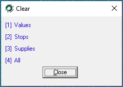
1 Values: Set all voltages and currents shown to 0.
2 Stops: Removes all power stops.
3 Supplies: Removes all power supplies.
4 All: Will set all voltages and currents to 0 and remove power stops and power supplies.
.2 ApArea
. 2 ApArea (Append Area) Append only those networks connected to the current powering area (as defined by power stops). While this is principally for the appending of networks with active taps (which preclude compression), it may be used for any network with attached legs, particularly if the network being powered has too many attached legs to append all at once.
..2 Append
. . 2 Append This function is the same as the AutoAppend function available in the Entry menu. When invoked, it will append all of the feeder legs that originate from the network in memory.
3 CarryPs
3 CarryPS Turns on and off the carry power supply function that allows you to pick up a power supply and carry it until you put it down by pressing 3 again. This function also automatically recalculates the power requirements as the cursor is moved even if it is invoked where no power supply is present. Note that CarryPS toggles the CarryPS indicator on and off.
.3 CarrLE
. 3 CarryLE Picks up active the device at the current node. Once a device has been picked up, it will move along with the cursor until it is put down by pressing . 3 again. Note that any method of moving the cursor (Jump, Page Up, Page Down, etc.) will also move the active device. When an active is being carried, the CarryLE indicator is set to ON.
..3 Unapnd
. . 3 Unapnd Automatically strips off any branches previously appended with the Autoappend or AppendArea functions.
4 Recalc
4 Recalc (Global) Recalculates voltage and power requirements from each existing power supply in the network. This function has no effect within power boundaries in which no power supply has been placed.
.4 Report
. 4 Report Generates a listing of actives, taps, splits, and power supplies in the current powering area. Also, lists location, device type, voltage, current draw, downstream current, voltage range, along with quantity and type of cable leading up to each device. If running a report on a powering area that is connected to another network through a PCD, the report must be run from the network containing the power supply.
..4 Trans
. . 4 Trans Displays an indexed list of transformers from the spec file. Select the index number for the desired transformer or enter 0 to remove.
5 Test
5 Test Lists all powering errors. See theTest Errors section later in this chapter.
.5 CarCplr
. 5 CarCplr (Move Coupler) Allows easy movement of coupler(s) and attached branch(es). Invoking this command will pick up one or both couplers at a node. If there is only one split at a single node, this function will always pick up the branch and its coupler. If two branches begin at a node, invoking it from the footage, amp, or supply columns will pick up both couplers. Invoking it from either coupler column will only pick up the branch that starts in that column. Note that if two branches are fed by a three-way coupler and only one of them is carried and then placed at a different node, the three-way coupler will be deleted. Once this has been invoked, a "Carry Coupler: will appear next to the button, indicating that carry coupler is active. When the cursor is moved to another location and . 5 is pressed a second time the coupler will be moved to that location. Note that this may be used to move a branch between the first and second positions on a single node.
6 Locate
6 Locate Will find the location within the current powering area where a power supply could be placed to give the minimum current requirement, and will calculate voltages and current as if a power supply were placed at that location.
.6 TstArea
. 6 TstArea (Test Area) Same as 5 Test but only for the powering area that the cursor is in. A power area is defined by placing power stops.
7 BOM
7 BOM (from Powering menu) Calculates and displays the Bill of Materials for the powering area (as defined by power stops) in which the cursor is located. This includes all feeder legs presently attached to amplifiers within the powering area. The Print Bill of Materials window for this command includes a "BOM Entire System" option, which will calculate a BOM for the entire network in memory and all attached legs. For the BOM to be calculated correctly for multi-level attachments (amp windows leading to legs that have amp windows leading to still more legs, etc.), the legs with those attachments must be Appended at the time the BOM is calculated. For example, BOMs for attached networks more than one level deep may not be included if only AppendArea was used; all networks should be Auto appended to the topmost network. To obtain a printout of the BOM, press 1 while in the screen display. The results may then be sent to a printer or file.
.7 Loc Mnu
. 7 Loc Mnu (Locate Menu) Similar to 6 Locate, but with the following options:
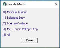
0 Minimum current: Same as 6 Locate.
1 Balanced Draw: As close to equal current draw as possible in at least two directions from the supply.
2 Maximum Low Voltage: Select the placement that will result in the lowest voltage being as high as possible.
3 Minimum Square Voltage Drop: Find the point with the minimum sum of the squares of the voltage drop at all powered devices.
4 All: Run all power options in this menu.
8 Calc
8 Calc Calculate the voltage and power requirements for the current powering area as if a power supply were placed at the cursor location.
.8 NIUtest
. 8 NIUtest Invokes NIU Powering Analysis (seeNIU Powering Analysissection later in this chapter) menu.
9 Node NIU
9 Node NIU Toggles the NIU on or off at the cursor location.
.9 BR NIU
. 9 BR NIU Toggles all of the NIU’s in the current branch on or off.
./ Dist
. / Dist (Calculate distance) Asks for a node in the current network and then calculates the total distance between the specified node and the node at the cursor position. These nodes need not be in the same branch nor need one be fed from the other.
.+ Name
. + Open Amplifier Definition Window Within this function you may specify a name for the amplifier at the cursor location and assign the feeder legs that begin from that amp/LE as well as move to, rename, or delete these feeder legs. This command will have no effect if no amplifier is present at this location. SeeChapter 5: Utilities, sectionAmplifier Definition Window for more information.
..+ Note
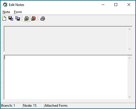
. . + Note The “Sticky Note” function allows entry of a text note at any node in the network. This note may be used to enter any information desired. If your project calls for the same basic information at many locations, you may want to create a form. A form is a file that can be attached via a note and used multiple times through out the network(s). You may create this form in any text editor and save it as <filename>.F00. Once the changes to the note have been saved, the Design Assistant will display a yellow musical note ♪ on
the line between the cab and lv columns.
PCD - Centralized and Distributed Powering
With the ever-diminishing size of serving areas in today’s popular HFC designs, it is often desirable to power multiple networks or fiber nodes with one centrally located power supply by connecting them together with powering cable. This is what we refer to as “centralized powering”. It is also sometimes desirable to insert power in multiple places in the same network or fiber node by running power cable from the power supply some distance along an express run to the power inserter, thereby maximizing the operating voltages. This is what we refer to as “distributed powering”. Beginning in version 3.0, the Design Assistant simplifies these popular powering scenarios by giving you the ability to distribute power to separate parts of single networks and by giving you the ability to connect multiple networks together.
Either scenario described above requires the use of what we call a Power Connecting Device or PCD to create the desired connections whether within a single network or spanning across multiple networks. To place a PCD, put your cursor in the coupler column, press 0 to alter and enter 1000 as the id number. This will display a dialog box providing the option to either create a new connection or to connect to an existing open PCD (anytime the new connection option is chosen, it creates an “open” PCD). Make your desired selection and press ok.Note: PCDs may be placed while in the Design, Power, or Active Entry modes and also note that the program will not allow the creation of loops when placing PCDs.
To create a connection within the same network for distributed powering, place power stops so that your PCD will not create a loop, place power inserter(s) with the distance back to the power supply on the branch the power inserter creates, and place the PCD at the end of that distance. To create a connection between two (or more) networks, open another instance of the Design Assistant being sure that the networks you wish to connect are open in each instance of the Design Assistant (for example Node1 is open in one Design Assistant window and Node2 is open in the other Design Assistant window). Once the desired networks are open, place a power inserter in one or more of the networks with the distance needed to connect the networks on the branch the power inserter creates and insert the PCD.
Once the connections have been created it is possible to jump between the connection points by simply double clicking on the network name displayed in the coupler column. If a network is opened that has another network connected to it for powering purposes, the Design Assistant will automatically start a new instance and try to open the connected network whenever it tries to calculate powering information.
Be sure, that if you are creating connections within multiple networks, that each network file is saved individually to ensure that all the connection information is retained correctly. Also, be sure to save all connected networks if a connection location has been changed in any of the networks. It is important to keep in mind that the Design Assistant stores PCD connection information by using the branch and node numbers. Therefore, if you make any change to the branch and node structure upstream of a PCD, you are actually modifying the connection location and consequently need to save both networks. Commands that may change the branch and node structure include delete, insert, join, break, etc.
Network Interface Unit
.8 NIUtest (Network Interface Unit Powering Analysis)
Allows you to perform various tests on a network using system-powered telephony Network Interface Units.
NIU Tests on Multiple Networks
If performing an NIU test on multiple networks connected through PCDs, the test should be run from the network containing the power supply.
1 Statistical
This is probably the best test to run on any given powering area to determine the chance of failure during normal operating parameters. Due to the variable nature of NIUs, the variation in take rates, and differing usage patterns, it is not possible to accurately determine probable power consumption in just one test. Therefore, the statistical analysis runs 1000 trials within the current powering area to help determine different possible powering scenarios.
It is helpful to think of the statistical test as a sort of “Monte Carlo” test. Each trial consists of “rolling the dice” and randomly placing NIUs based upon the penetration percentage defined in the Parameters file. Once NIU locations have been randomly determined, the Design Assistant revisits each location and once again “rolls the dice” at each NIU location to determine the statistical probability that this particular phone is off hook, ringing, or otherwise in use.
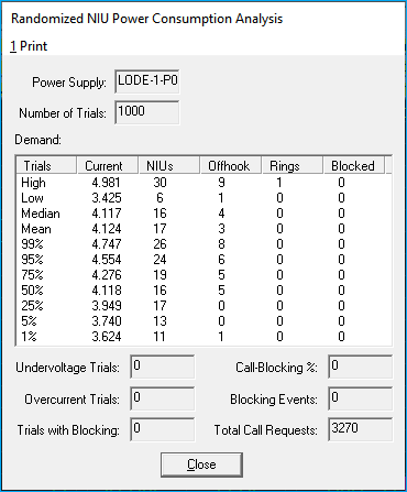
Once the 1000 trials have been completed, a window similar to the image below will be displayed:
Pressing any key will remove this display box from your screen.
A quick analysis of this display reveals the following:
✔ 1000 trials were run on power supply “ps2”
✔ The highest current in any of the 1000 trials was 6.008 during which 20 NIUs were placed, 7 of them were off hook, 2 were ringing, and there were 0 blocked calls
✔ The lowest current in any of the 1000 trial was 4.774 during which only 4 NIUs were placed, 0 was off hook, 0 were ringing, and there were 0 blocked calls
✔ The median power consumption was 5.287 (14 NIUs placed, 0 off hook, 0 ringing, and 0 blocked calls)
✔ The mean power consumption was 5.296 (12 NIUs placed, 2 off hook, 0 ringing, and 0 blocked calls)
✔ 99% of the trials had a total current consumption of 5.769 (with 19 NIUs, 4 off hook, 1 ringing, 0 blocked) or less.
✔ 95% of the trials had a total current consumption of 5.638 (19 NIUs, 1 off hook, 1 ringing, 0 blocked) or less
✔ Further breakdown for 75%, 50%, 25%, 5%, and 1% of the trials
✔ There were no under voltage trials
✔ There were no over current trials
✔ There were no trials with blocked calls
✔ There were 2144 call requests
All in all, this is a pretty stable powering area. This analysis can be interpreted in a number of ways. For instance, some may decide that if there is no more than a 75% chance for failure then it is OK while others may decide that if there is even a 1% chance for failure then the area must be reevaluated. Whatever your parameters may allow, this analysis should provide enough information to make an informed decision.
2 Worst-case
Provides the ability to perform a peak-usage risk assessment by allowing the modeling of periodic "peak phone usage" powering scenarios to ensure that your broadband telephone design falls within your power supply's capabilities at all times.
The worst-case analysis allows you to specify a different penetration percentage than is set in the spec files as well as specify how many lines should be forced off- hook in the current powering area. It then selects NIU lines in such a way that the overall current draw is maximized. Pulling one line off-hook per NIU beginning at the NIU with the lowest operating voltage, and then proceeding in order of increasing operating voltage do this. If the number of off-hook lines you've specified exceeds the number of NIUs in the current area, additional lines will be pulled off-hook starting, once again, from the NIUs with the lowest operating voltages until the desired number of lines are off-hook. An estimated average value of additional current draw due to ringing will also be added into the calculations, to produce the worst-case current draw.
The display window for Worst-Case Analysis shows the following details:
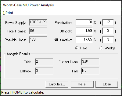
The first line displays the type of power supply and the location of that power supply. The next two lines display the total house count (including MDU units) and total lines possible within the active powering area. The total lines possible is derived from the total house count above, the number of phone ports specified in the NIU specifications on the Base NIU tab in the Couplers file, and any specific NIU arrays that may have been placed in MDU windows during design of this powering area.
Penetration:
Displays, in brackets, the current NIU penetration percentage. It automatically defaults to the value set in the specification files. The number to the right in parenthesis is the number of phone lines equal to the specified penetration percentage. It is possible to modify either the percentage or the lines to simulate various worst-case tests.
Offhook: Displays, in brackets, the current percentage of active NIUs that will be pulled off-hook during the test. The number to the right in parenthesis is the number of phone lines equal to the specified off-hook percentage. It will default to the value set in the spec files. For instance, if the spec files specify an off-hook of 15%, then the number displayed here is 15% of the active phone lines determined by the penetration percentage. The Penetration percentage includes additional line percentage if any is specified in your Parameter specs. In the screen shot displayed above, 5 lines are equal to 15% of the 26 phone lines determined by a penetration percentage of 20, with 10% additional lines.
Off-Hook Limit
The off-hook limit specified on page one of the Parameters file overrides the value that can be set here. In other words, if you try to set an off-hook value in this test that is higher than the off-hook limit specified in the Parameters, the worst-case test will revert back to the limit set in the spec files. It is possible to experiment with higher off-hook limits by temporarily setting the off-hook limit in the Parameters to “0”. It is possible to modify either the percentage or the lines to simulate various worst-case tests.
NIUs Active: This sets a limit on the number of NIUs to be activated. The effect of this is to further concentrate the power-consuming line activation’s. The smaller the number of NIUs allowed to be active, the more localized the powering problem becomes. An NIU being active means that at least one of its lines is off-hook. It is not possible to have a larger number of NIUs active than you have off-hook lines. It is possible to modify either the percentage or the lines to simulate various worst-case tests.
Halo/Wedge: Worst-case power consumption occurs due to high, localized activation of NIUs that are distant from the power supply. Two patterns may yield this situation. The first is a “Halo” where the NIUs are randomly distributed around the outer edges of the powering area. The second is a “Wedge” where the localization occurs primarily on one main branch or express line of the network. Though different criteria are used to develop the increasingly stressful scenarios with each of these options, results may often be very close to the same due to other characteristics of the power delivery system.
Pressing Home will invoke the test that displays a second window showing the following details:
Trials:
Each time another stress scenario is developed, the power calculations are run again to determine the new load. “Trials” shows how many iterations of this were performed.
Off-hook:
Displays how many phone lines were actually pulled “off-hook”.
Current Draw:
Displays the worst-case current draw. This is the point at which a more stressful scenario could not be created within the worst-case setup specifications.
Fails:
Displays a yes or no to indicate if any failure scenarios were generated. A yes indicates that either an under-voltage or an over-current condition existed on an NIU or active device. The actual voltage at an NIU or active device going below the Minimum Voltage specification causes an under-voltage condition. This condition can sometimes be fixed by moving the power supply to a more centralized location. An over-current condition indicates that there was too much current passing through a device. The power passing capacities of devices are specified on the General Parameters tab in the Parameters file.
Clear Worst Case
When the Worst Case function is invoked, power calculations will be set to Worst-case Simulation mode. This is indicated by a WorstCase text display to the right of the CarryLE indicator. They will remain in this mode until the Clear sub-function of . 8 NIUtest is called or the Powering menu is exited by switching to another mode.
3 Failure Point
This test calculates the number of lines off-hook if and when an NIU or any other devices falls below its minimum voltage in the current powering area. Only minimum voltage is checked by this test. All other possible failures such as excess current draw or excess current through a certain device may be checked for with the test and test area functions in the Powering menu.Note: Meta NIUs are not used in this test.
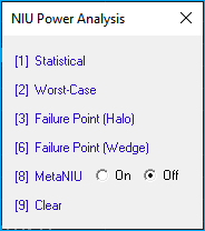
8 MetaNIU On/Off
Toggles the use of MetaNIUs on or off. MetaNIUs are defined on Meta NIUs tab in the Couplers file and are used to further define how a customer uses their phone. MetaNIUs can be toggled on or off in specific powering areas for use in the statistical test to more accurately model the probable powering needs of your system. To use the MetaNIUs for the statistical analysis, toggle this setting to on (an M will appear in the upper left area of the menu). When toggled on, the statistical analysis will use MetaNIUs exclusively (except where NIU arrays have been explicitly placed through the MDU Window).
Powering Area
If powering area includes connection to another network, be sure MetaNIU is turned on in both instances of the Design Assistant.
9 Clear
Resets the powering calculation mode to Normal. When NIU Worst-case analysis is used, the specified distribution of off-hook lines will continue to be used for all powering calculations until Clear is used, the Powering menu is exited, or either of the NIU analysis routines is used again. Unless the powering calculations are in Worst-case mode (as indicated by the red flag on the top-left corner of the screen), Clear will have no effect.
Complexity of Analysis
Due to the complexity of the analysis and the number of repetitions in the various NIUtest options, any given test may take a minute or so to complete. You may break out of any of these tests at any time by pressing the Escape key. The trial currently running will complete before the Escape takes effect. Trial conditions will be based on NIU power requirements placed in the Couplers file, and penetration and status information placed in the Parameters file.
See Building Specification Files for more.
Test Errors
Following is a list of all the errors produced by the 5 Test and . 6 Test Area functions of the Powering menu. All errors displayed in red are out of spec; those displayed in yellow are marginal.
Excess current draw at: The current draw is too high for the power supply used.
Excess current thru: The amount of current being drawn through the specified device exceeds the maximum limit (“Max A”) set on the General Parameters tab in the Parameters spec files.
Insufficient voltage for:
Voltage at specified device dropped below Vmin set in Actives spec file for amplifiers, the Couplers spec file for NIUs, or Taps spec file for powered taps.
Bucking power at: There are two power supplies within the same powering area that have not been separated by a power stop.
Open PCD at: A Power Connecting Device has been placed at this location, but the connection to another PCD has not been completed.