Reports
Print Pull-down Menu
The Print pull-down menu gives you options of viewing and/or printing various reports about the data stored in the Design Assistant. All of the reports listed in the Report Generation menu can be viewed or printed. The available reports are broken down into four main categories: Specs, Networks, BOM, and Miscellaneous.
Specs
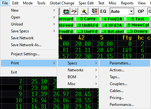
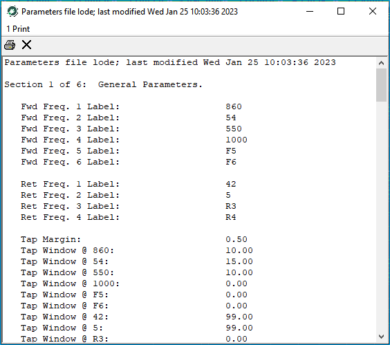
To print any of the currently loaded specification files, hold the cursor over Specs and click on the desired spec file (Parameters, Actives, Taps, Couplers, Cables, Pricing, or Performance). The chosen spec file will be displayed in quick report format providing the opportunity to view it scrolling from page to page, if desired. It is also possible to save it to a file for customization or printing at a later date.
Networks
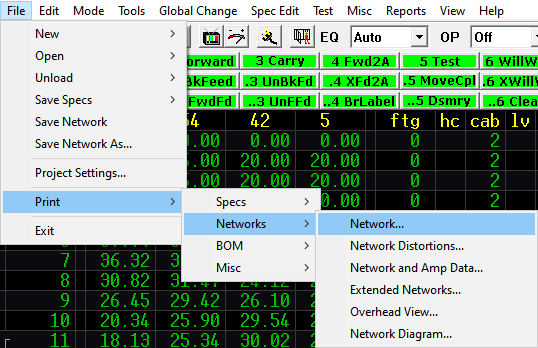
There are six options displayed under the Networks fly-out option: Network, Network Distortions, Network and Amp Data, Extended Network, Overhead View, and Network Diagram. When any of the network printout reports are chosen, the desired report will be displayed in a print window.
Once the report is displayed there are two options:
- View and scroll through the report – pressing Escape will clear the report.
- Print the report by pressing 1, selecting the desired printer and pressing OK.
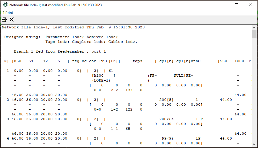
Network
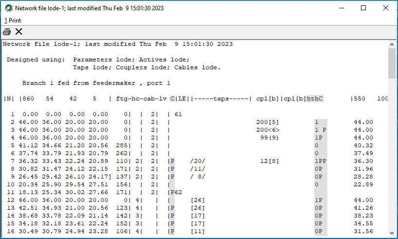
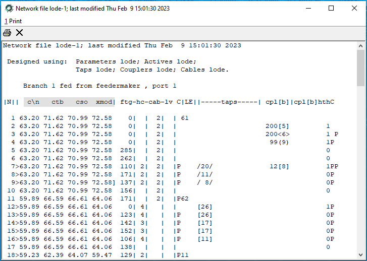
The network option will produce a report that looks very similar to the Design Assistant network while in the Design menu with three additional columns.
-
The
Ccolumn - located betweenlvandLE, lists the pin-type connectors from the cable to the first piece of equipment on that line. -
The
hthcolumn - located to the right of thecpl [b], lists the number of housing-to-housing connectors at the end of that line. -
A second
Ccolumn - Next to thehthcolumn, lists any pin-type connector at the end of that line.
Network Distortions
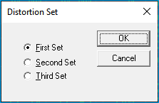
The Network Distortions option prompts you to choose either the First, Second, or Third set of four distortions as set up in the specifications files.
It looks similar to the network printouts except it displays distortions in place of the frequency columns.
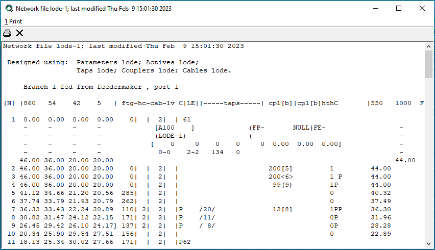
Network and Amp Data
The Network and Amp Data report is the same as the Network report except the screen is expanded at amplifier locations to display pad/EQ values, etc. The extended network report expands the screen at every node to display amplifier data and tap output levels.
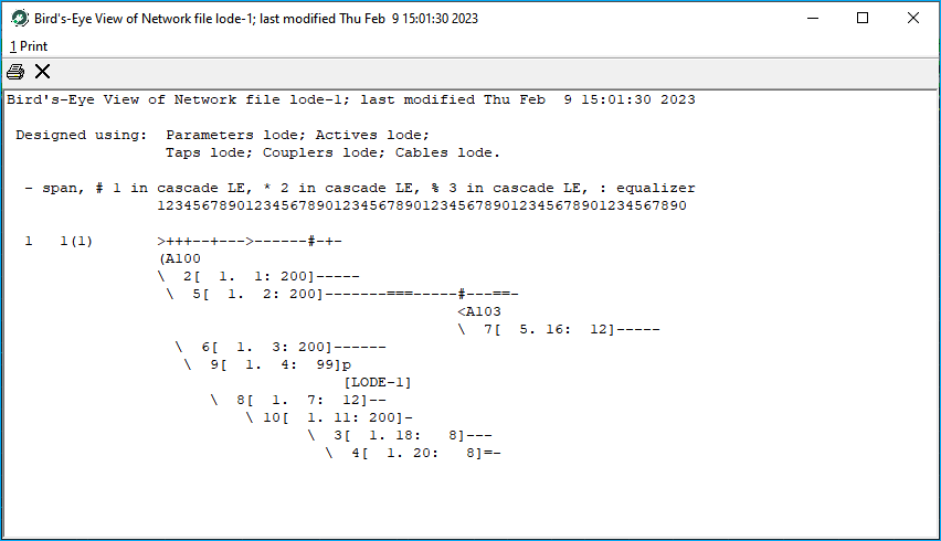
Overhead View / Network Diagram
The Overhead View and Network Diagram reports provide a “stick diagram” of the network in memory.
Overhead View
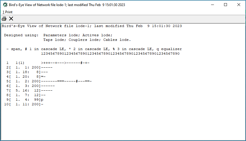
Network Diagram
Extended Network
The Extended Network displays frequency signal levels in the network printout.
BOM
The BOM or Bill of Materials fly-out contains five reports:
- Control file BOM
- Single Network BOM
- Map BOM
- Powering BOM
- Analysis
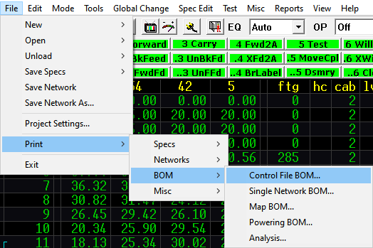
Control File
To use the Control file BOM report you must have a valid control file loaded. A control file is a file containing a group of networks. The Control file BOM report takes this group of networks and adds the BOM information to produce an overall Bill of Materials.
Creating a Control File
Creating a Control file is covered in detail later in this section.
Single Network
The Single Network BOM produces a Bill of Materials report for the network currently in memory. The map BOM report allows for creation of the Bill of Materials by map #, if entered in the Entry screen while creating the network. The Powering BOM calculates the Bill of Materials based upon power supply boundaries. The Analysis report produces a Bill of Materials based upon the networks in the current Control file, but it redesigns each network using a forward execution method. The Analysis report could be helpful to see what the effects of a different cable size or tap output level may have on a large group of networks.
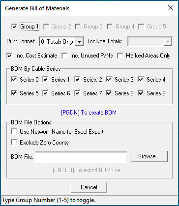
When any of the BOM reports (other than Map BOM) are selected, a Generate Bill of Materials window similar to the following will appear on the screen:
Print BOM pages
The Control file has the capability of grouping networks (from different directories if desired) into five separate groups by specifying a path on each page and adding the desired networks to the Control file. The Group check boxes allow you to select/unselect the pages you want to include in the BOM. Pages does not refer to how many pages the BOM printout will be. The default is to print out all the pages of the Control file that contain networks.
✔ Group Option
This option is only available for Control file BOMs not Single Network or Map BOMs.
If the BOM report is to be generated by power supply, page 1 contains the BOM for the trunk station and page 2 contains the BOM for the attached feeder legs (if any).
Print format
There are five options for the BOM format. Totals only displays the BOM totals for each page in a single column that contains all equipment used, both aerial and underground (Format 0). Also, you may select aerial and underground in two separate columns (Format 1), aerial, underground, and totals in three columns (Format 2), aerial only in one column (Format 3), and underground only in one column (Format 4).
Default: Totals only
✔ Include totals
This option is available for the Control File BOM. Extra columns are added to the BOM showing either the total of the combined pages, the difference between pages, or the total and difference.
Default: NO
Include cost estimate
Tells the Design Assistant whether to calculate a cost estimate for the Bill of Materials based on the Pricing file. If no prices have been entered into that file, the default is NO; if prices have been entered, the default is YES.
Include unused PNs
Include lines in the BOM listing all part numbers entered whether there are any used in the network(s) or not.
Default: NO
Marked area only
If the BOM is to be calculated for a single network, you have the option of calculating the BOM for only the areas that have been marked instead of for the entire network. These need not be contiguous. See Chapter 5Entry Menu for information on how to mark specific areas within the network.
Default: NO
BOM by cable series
In the Single Network BOM you may tally your Bill of Materials by cable series. Using the mouse, select the first number of the series that you wish to BOM. For example, picking a 3 and a 5 here will BOM just the cable and equipment fed with 300 and 500 series cable.
Once you are satisfied with the options chosen, press PGDN. Press Cancel to return to the Design screen without displaying the report. You should be viewing the selected BOM, but this BOM has not yet been sent to the printer. In the report screen, the Page Up and Page Down, along with the Left Arrow, Righ Arrow, Up Arrow, and Down Arrow keys all operate to scan through the text. Listed are the part numbers and totals for all of the parts used to design the network in memory.
To print the report, press 1 or select Print to display the Windows print dialog box. Select the desired printer and press OK.
There are two other options for printing many of the reports
- Print to file
.TXT - Print to Excel format or
.XLS
To print to a text file, you must first install the Generic Text Only printer driver supplied by Windows. Select this option as the desired printer whenever you wish to print to a text file. If you are not familiar with how to install a new print driver, please consult Microsoft Windows documentation.
It is also possible to print some Design Assistant reports in a Excel format. To do this, simply type the name of the Excel file followed by .XLS, for instance test.XLS next to Excel file name in the print display box. Printing to a .XLS file allows for customized spreadsheets containing Bill of Materials or Active Report information. This feature allows the user to customize not only the look of the report, but also the content. BOM File
Options include Use Network Name for Excel Export and Exclude Zero Counts. By default the Excel files are saved to the Network folder as setup in the Project Settings or the user can Browse and select a destination folder. After selecting the path and filename Press Enter or select Enter To export BOM File and the Excel BOM will be created.
Misc
There are nine miscellaneous reports available: Macro Summary, Active report, Control File Active report, Tap Distribution report, Performance Distribution report, Network Notes, MDU report, Power Supply report, and Control File PS report.
Macro Summary
The Macro Summary report displays a listing of all currently assigned and saved macros. It lists the hot key used to invoke the macro, the length or number of keystrokes used in the macro and the macro text description (if any). Press 1, select the desired printer, and press ok to print this report.
Active
The Active report is a summary of all pertinent information about the actives in the current network. The Active report will provide the amplifier type, name, inputs, outputs, pads/eqs, and much more for every active device in the current network. The Active report is only available in Excel format. Enter the file name and press [Enter]. The file has been created and saved in the directory specified in your Project settings..
Control File Active
The Control File Active report is the same as the active report except instead of producing a report based on the current network; it produces a report for all the networks listed in the current Control file.
Tap Distribution
The Tap Distribution report allows you to analyze how many of the currently loaded network's taps are above or below the minimum tap output specified at each node. This report shows the number of taps and tap ports above or below the specified level and breaks them down in .25 dB increments. Press 1, select the desired printer, and press ok to print this report.
The Performance Distribution report provides a breakdown of the expected performance for each type of distortion (c/n, ctb, etc) at every tap in the currently loaded network. The report breaks down the performance levels in one dB increments. The number of taps and tap ports operating at the various performance levels are tallied in their respective columns. Also included for each 1 dB increment is a percent total indicating what percentage of the taps in the network is operating at that level or above.
Network Notes
The Network Notes report creates a text file containing the location, (Branch/Node) and content of each note.
MDU (Multiple Dwelling Unit)
The MDU report creates a text file containing the location, (Branch/Node) and content of each MDU.
Example:
MDU Report for network: lode-1
Printed on Thu Feb  9 15:01:35 2023

Branch: 1  Node: 14

ftg  cpl   cb   lv   qty
10    2   14    0     4
0     0    0    0     0
0     0    0    0     0
0     0    0    0     0

tap#(port) MDUline(Array#) CodeNumber(drop#)
1(1) 1(1)   2     16.42  12.99  42.98  41.98  16.62
1(2) 1(2)   2     16.42  12.99  42.98  41.98  16.62
1(3) 1(3)   2     16.42  12.99  42.98  41.98  16.62
1(4) 1(4)   2     16.42  12.99  42.98  41.98  16.62
MDU Window
This print out reflects the MDU Window Array
Power Supply
The Power Supply report creates an Excel spreadsheet containing the location and values of all power supplies in the currently loaded network.
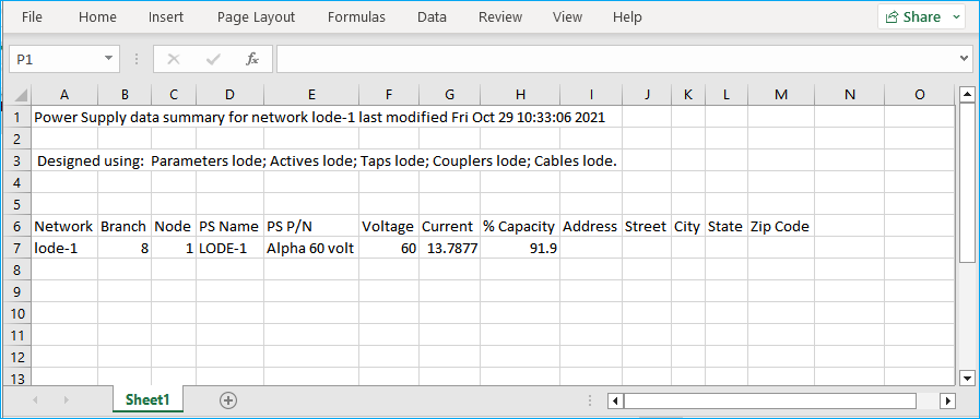
Control File Power Supply
The Control File PS report creates an Excel spreadsheet in the same format as the Power Supply Report which contains the location and values for all power supplies in the control file currently loaded.
Creating a Control File
A Control file is a file that contains a group of networks, the contents of which are added together to create cumulative Bills of Materials or active reports. To create a new Control file, go to the File pull-down, select New, and then select Control. A dialog box will appear prompting for a new file name, enter the file name and press OK to display the create
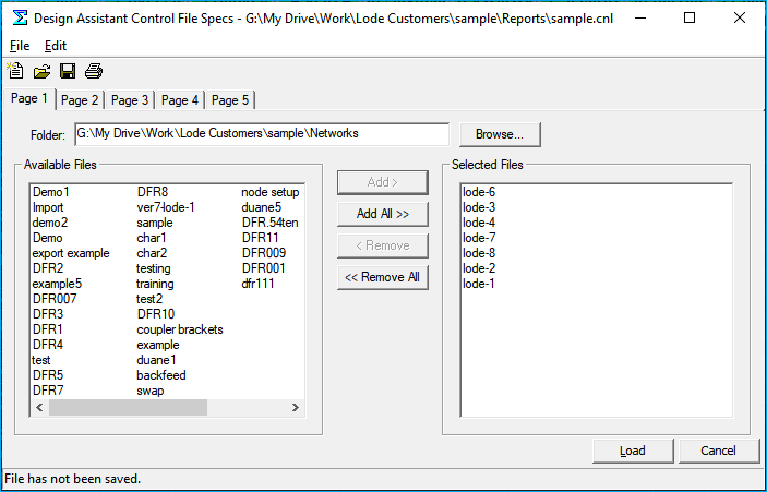
This simple dialog box is used to create new Control files or edit existing Control files. The File pull-down provides the options of opening a Control file, saving a Control file, and saving a Control file as a different name.
To begin creating a new Control file, press the Browse button and choose the directory where your networks reside. The networks in that directory will be displayed on the left side. Select the desired networks (hold the Ctrl button to pick multiple networks) and press ADD >. The highlighted networks will be moved to the right side. To include all the networks in this directory in the Control file, press Add All >>.
Notice the tabs along the top of the dialog box labeled page 1, 2, 3, 4, and 5. This allows the Control file to include networks from separate directories. If you wish to take advantage of this functionality, click on the Page 2 tab and follow the directions outlined above.
To remove files from a Control file, select the desired files on the right side of the box and press < Remove or press << Remove All to remove all the networks.
Once you are satisfied with the chosen networks, save the file and press OK and you are ready to use your newly created Control file.
Missing Control File Window
Sometimes your control file window may appear to be "missing". This usually occurs when a user has two monitors and The Design Assistant is on the secondary monitor. To resolve the issue, temporarily move The Design Assistant window to the primary monitor.