Utilities
The Design Assistant contains many commands that are functional in multiple menus. We will discuss these utilities in detail. Also, there is one global command, MACROS, that is functional in every menu. The MACRO command allows you to record repetitive keystrokes that you can play back at any time. Due to the potential of Macros, we have dedicated an entire section to it.
More on Macros
See Macros for a complete overview of the MACRO command.
Jump
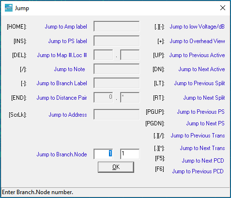
One of the most used commands in the program, this command includes a host of ways to move quickly to other parts of the network. The simplest and most obvious use is to enter in the number of the BRANCH . NODE where you want the cursor to move. When first opening the JUMP command your cursor will be placed in the JUMP TO BRANCH.NODE input. You enter the location in the form of BRANCH . NODE.
Tip
Attempting to move the cursor beyond the last branch or the last node in a branch will move the cursor to the last branch or node, as appropriate.
If either branch or node is not specified, it will be left unchanged (e.g., if the cursor was at location 1.7, typing 5 would move the cursor to 5.7; . 5 would move the cursor to 1.5).
Additionally, several other options exist at the Jump menu.
Amp
HOME Jump to Amp label
The cursor will move to the input for an amplifier label and then jump to its location. The entire label need not be entered. This command will search for the first amplifier whose label begins with the search text. The text search is not case sensitive.
Amp Label
The Amp Label is also referred to as an amp or active ID.
HOME HOME Repeat amplifier search
The cursor will be moved to the next amplifier after the cursor's current position that matches the search string.
Power Supply
INSERT Jump to power supply label
The cursor will move to the input for a power supply label and then jump to its location. The entire label need not be entered. This command will search for the first power supply whose label begins with the search text. The text search is not case sensitive.
INSERT HOME Repeat power supply search
The cursor will be moved to the next power supply whose label begins with the search text.
Note
/ Jump to Note
Searches for a text string within a comment or sticky note. The entire comment does not need to be entered. This command will search for partial text strings. The text search is not case sensitive.
Branch Label
- Jump to branch label
Searches for a branch label or name.
Low V/dB
. - Low V/dB
Locates the lowest voltage if in the POWERING mode or the lowest high channel signal level if in the DESIGN mode.
Distance Pair
END Locate distance pair
Will prompt for one or two footages in the form FOOTAGE 1 . FOOTAGE 2. The cursor will be moved to the first pair of footages matching the search pair, even if they are separated by a single zero node or coupler. If the second footage is not entered, the cursor will be moved to the first matching footage.
END END Repeat footage search
The cursor will be moved to the next footage or footage pair matching the search footage(s) entered the last time the footage search command was used.
Map / Loc
DELETE Search for map#/loc#
Will prompt for a map and location number in the form of MAP .LOCATION. The cursor will then be moved to that position. If only a map number or a location number is entered, the cursor will move to the first node that matches that map or location number.
DELETE DELETE Repeat map and location number search
The cursor will be moved to the next map and/or location number matching the search string.
Overhead view
+ Overhead view
Puts full-screen overhead view of network on screen. Arrow keys may be used to move the cursor to the desired node. The number of the node under the cursor will be displayed in the upper-left corner of the screen. Pressing ENTER will return to the menu from which jump was invoked with the cursor located at the node selected. Pressing ESCAPE will return to the menu without moving the cursor.
Previous Active
↑ Move to the previous active
Next Active
↓ Move to the next active
Previous Split
← Move to the previous split location
Next Split
→ Move to the next split location
Previous Power Supply
PAGE UP Moves cursor to previous power supply location
Next Power Supply
Page DOWN Moves cursor to next power supply location
Previous Transformer
. / Jump to previous transformer
Next Transformer
. * Jump to next transformer
Next PCD
F5 Jump the Next PCD
Previous PCD
F6 Jump to the Previous PCD
Address
SCROLL LOCK Jump to Address
The entire address does not need to be entered. This command will search for partial text strings. The text search is not case sensitive.
Amplifier Definition
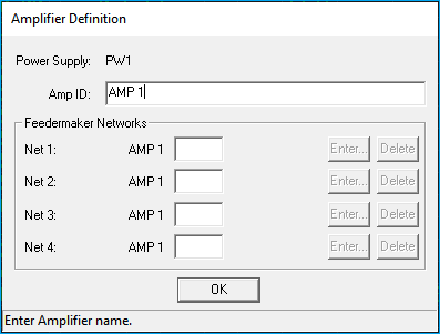
. + Name
Opens the Amplifier Definition Window from any Design or Powering mode. This command is displayed in DESIGN, POWERING, and ENTRY modes. The Amplifier Definition Window allows the entry of a unique identifying name up to 256 characters for each amplifier in a network.
Name in Entry Mode
The menus in the ENTRY mode are all prefixed with a -, thus the NAME command is - . + in ENTRY mode.
Simply type in the name for that amplifier, followed by the ENTER key, then press PAGE DOWN.
Power Supplies
Names up to 256 characters long may be applied to power supplies as well by pressing . + while the cursor is on a power supply.
Character Length
While only fourteen characters for each amplifier and six characters for each power supply are displayed on the Design screen, the full length name is retained in memory.
Feedermakers
In addition, up to four extensions of one or two characters each may be specified for each amplifier in the Feedermaker Networks section of the Amplifier Definiton Window. These extensions, appended onto the amplifier name, are the names of the feeder networks that begin from this amp.
Increment
After an amplifier has been named (during one design session), the name is retained and displayed the next time the Amplifier Definition Window is opened. Pressing + will increment the last number or character in that amplifier’s name.
For example:
- Name the first amplifier
DEN01-01and move to the next amplifier. - Press . + and the name
DEN01-01will be displayed on the first line of the Amplifier Definition Window. - Press +and the name will change to
DEN01-02. - Finish the naming of the second amplifier by pressing ENTER followed by PAGE DOWN.
You may change the name of the amplifier or the networks attached to it at any time and if the networks connected to the amplifier already exist, they will be renamed automatically.
Navigation
↑ ↓ will move the cursor up or down between entries within this window.
ESCAPE or NUM LOCK Closes the window, saving the information within.
Navigation Feedermaker Networks
→ If a number is displayed in brackets to the right of the two-character extension for a given network, this signifies that the compressed legs corresponding to this network have been appended using the AUTOAPPEND or APPENDAREA functions. If AUTOAPPEND has been used and no number appears there, this indicates that either the network has not been entered or that the network does not contain any active devices. If such a number is displayed, pressing the right-arrow key will move the cursor to the starting point of the appended branch indicated.
PAGE DOWN If pressed when the cursor is on one of the network positions in the window, this will create that network and prompt to save the network if any changes have been made. Or, if the network had been previously created, it will load that network, again prompting for a save if any changes have been made.
Save Changes
If you do not save your changes, they will be lost -- this includes any changes to the names in the Amplifier Definition Window.
DELETE When pressed while the cursor is over one of the network positions, will delete the network extension from the window, optionally deleting the network of that name on disk as well.
When designating the number of feeder legs connected to the amplifier, if the network exists, the port and feedermaker number is displayed in the Amplifier Definition window. If it states “Not Found”, this represents the fact that you have told the Design Assistant that a particular amp will have a network connected here, but you have not yet created those networks.
Changing Names
Whenever network names are changed through this window, either through changing the amplifier name or the individual network name, if any of the networks named on disk do exist, they will also be renamed.
Legacy Networks
Use of feedermaker networks is not at all common in today’s architectures. The Amplifier Definition Window is used mostly to simply name amplifiers.
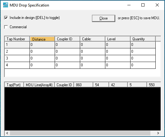
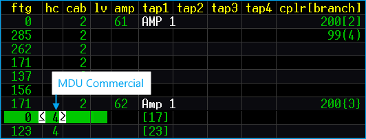
MDU Definition
Multiple Dwelling Unit (MDU) Definition Window
Opening the MDU Definition Window varies slightly depending on which MODE menu you are working in.
- 9 Set MDU in ENTRY mode displays the MDU Window.
. 7 Set MDU in DESIGN mode displays the MDU Window
. . 7 Set MDU in POWER mode also displays the MDU Window.
The MDU Window is designed to allow tap selection based upon drop length, drop coupler loss, drop cable type, and quantity of drops desired instead of minimum tap output and house count. The MDU Window is also where elaborate arrays of Network Interface Units (NIUs) may be input.
Network Interface Unit
More information on NIUs can be found in the Powering → Network Interface Unit
The Design Assistant will automatically tally up all of this MDU drop specification information and pick a tap that meets the criteria. Any time an MDU is defined at a node, this MDU information will override any tap level information specified in the LV column in the Design screen.
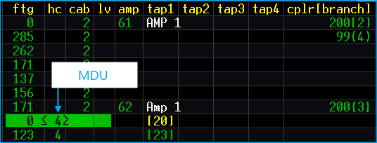
Once an MDU has been defined, the house count will be displayed in < > underlined angle brackets. By defining a node as having MDU information, the Design Assistant will separate the MDU house count from the residential house counts on the Bill of Materials.
Navigation
↑ ↓ ← → Move between entries in the MDU window.
ENTER Input data and move to the next entry. Pressed without first entering any numerical data, the ENTER key will use the last number input into the column being worked on to be entered even if the last such entry was in a different MDU window.
CLOSE Close [ESC] to save MDU
Pressing the CLOSE button closes the MDU window. You can also press ESCAPE or NUM LOCK on the keyboard, saving the information if at least one drop splitter has been specified.
Example
If your drop cables are all type 238 and you will be using only level 15 for the drop level you need only enter those in once when the program is first started. From then on pressing ENTER in the cable and level columns will automatically set the drop cable type to 238 and the drop level to 15. Of course, if you type another value in one of these columns it then becomes the default.
Options
 Include in design DELETE to toggle
With the INCLUDE IN DESIGN option checked (default) the MDU will be counted as a residential MDU and equipment specified in the window will be included in the Bill of Materials. Uncheck the box or press DELETE to remove this option. Unchecking will designate the house counts as NON-DESIGN-HC in the BOM
Non-Design House Count
DELETE Toggles between design and non-design status for the house count at that node. If non-design is selected, the house count will be included in the total house count for BOM purposes but no design will be produced for it. Angled brackets < > indicate non-design MDU's. Angled brackets that are underlined < > indicate standard MDU counts.
If you need to separate MDU counts from residential but do not wish to design the MDU with the window, you may count it as a “non-design MDU”. Any non-designed house count will be displayed in < > angle brackets as opposed to our normal underlined angle brackets. For any non-designed house count, the Design Assistant will not automatically pick any taps, but it will flag any level specified in the LV column in the Design screen (not the MDU window) that has not been satisfied at that node.
Commercial
A check mark in the COMMERCIAL option designates the MDU as a commercial drop(s). In the Design screen, the MDU location is highlighted by < > white underlined angle brackets. The house count is tallied as commercial in the Bill of Materials.
Columns
Tap Number
Number of taps that can be placed at one location.
You may define up to four separate taps to feed your respective drops. This accounts for a maximum of 32 drops. If your house count at any one node exceeds 63, the Design Assistant maximum, it will be necessary to “break up” the house count and put it on two nodes separated by a zero footage.
Distance
Refers to the drop length distance from the tap port to the end of the drop (demark, converter, TV, etc.).
Coupler ID
Refers to the COUPLER ID value from the COUPLER specs for the drop splitter.
Coupler Required
A COUPLER ID is required. If you do not want your design to include the loss and the drops created by a drop splitter, then you must define a fake zero loss coupler in your spec files and input that coupler ID here.
Cable
Refers to the CABLE ID value from the CABLE specs for the drop cable type.
Level
Refers to the SYSTEM LEVELS value from the PARAMETERS specs for the minimum level required at the end of the drop.
Quantity
Represents the number of drop ports required.
Coupler Effect on Quantity
The maximum value for this column is 8 since we have a maximum of an 8 port tap. If you have specified a 2 way drop splitter, then a QUANTITY of 8 will actually produce 16 drops.
MDU Array
Just below the columns at bottom portion of the MDU window is the MDU ARRAY. The array displays the results using the information provided in the TAP NUMBER, DISTANCE, COUPLER ID, CABLE, LEVEL, and QUANTITY columns previously described.
Tap Port The TAP(PORT) specifies which of the four possible taps feeds this particular drop and (PORT) specifies which port out of that tap.
MDU Line(Array#) The MDU line represents which line from the MDU drop specification box we are referring. Array# refers to the specific drop in the QUANTITY column that ends with the levels displayed to the right.
Coupler ID The COUPLER ID displays the drop coupler or NIU array ID number. If using an NIU, the number in the brackets represents which drop within a multi-drop NIU array the levels to the right are referring to.
Frequencies The remaining columns represent the signal levels at the forward high, forward low, return high, and return low frequencies.
Frequencies
These signal levels are the levels at the end of the drop, not the level out of the tap ports.
Example
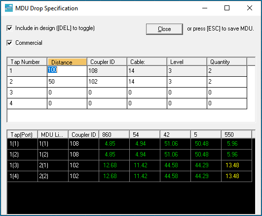
It may be easier to understand the MDU Definition Window with a more realistic real world scenario. The MDU window above represents a common usage.
Note
Many companies now account for MDUs by providing one port per unit. The scenario in this example is what the MDU Definition Window was originally designed for. Today's common usage is to count the number of MDUs and populate them in the Bill of Materials. This is done by leaving most columns empty except the coupler column since it requires a value. A "dummy" coupler is placed that has no loss.
The “102” here represents a 2-way drop splitter. If you are using Network Interface Units (NIUs) in your design, you will input the NIU drop array code here and it will be displayed in “[ ]” brackets to let you know that it is an NIU array. It is necessary to use the MDU window for all NIU nodes that require any NIU array configuration other than the default. The default NIU array configuration is defined on line 1 in Page 4 of the Couplers file.
In the example below the last line 1(4) means that this drop is being fed from the first tap - port four.
In this case, cable type “14” is RG 6.
Level “14” in these specs (SAMPLECITY) is defined as 4.5 dB at the forward high frequency and 1.0 dB at the forward low.
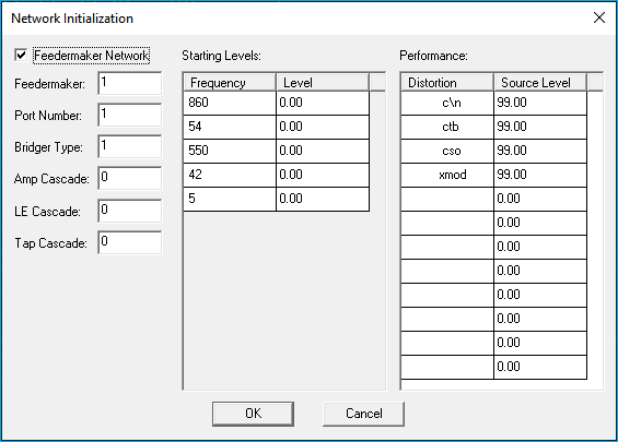
Network Initialization
The NETWORK INITIALIZATION WINDOW sets the starting signal levels and distortion levels for a network. It may be accessed at anytime from the ENTRY mode by pressing - 4 or from the TOOLS pull-down menu to change the starting signal levels for the current network. Anytime the Network Initialization command is invoked, the Design Assistant will display this box:
Net Init
The Network Initialization box will also be displayed once a new network has been created to set the starting levels for the new network.
Feedermaker
Clicking on the Feedermaker network checkbox signifies that the network being created is a feedermaker network. Since most networks in today’s architecture do not contain feedermakers, this option is normally not checked. When checked, the options to enter the feedermaker type, port number, and bridger type become enabled. If the Feedermaker option is checked, the signal levels will be set automatically and cannot be edited by a user. This is a safety feature to ensure that a network is not started with incorrect levels.
Bridger Type
Bridger types and their levels are defined on the Bridgers\Feedermakers\In line Eqs tab in the Actives spec file. A 1 in the Bridger type will start with the signal levels set for BR1 and subtract the loss of the feedermaker (and port) entered above.
Amp/LE Cascade
The Amp and LE Cascade make it possible to set the cascade that may already exist. Both of these will be set to 0 in most cases, but this feature makes it possible to track cascades accurately in the case of a plant extension.
Starting Levels
Sets the starting signal level at each of your 10 design frequencies.
Setting a Starting level
Setting a starting signal level will have no effect if that particular frequency is not enabled in the Parameters. If you are unable to modify the signal levels, check to be sure the Feedermaker network option is not checked.
Performance
Performance, sets the starting distortion levels at for each of your defined distortion types. If not sure, we suggest setting these levels to 99.
Buttons
OK will set the new levels and return to the network.
Cancel exits the Network Initilization Window without saving any changes.
Global Change
The Global Change pull-down menu is accessible from the Design mode and the Powering mode. Global change is excellent for quickly changing values across the entire network or a single branch.
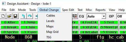
There are five options available:
- Cables
- Levels
- Maps
- MapGrid
- TSG [Taps Selection Group]
Selecting any of these options opens a separate menu as shown in Menus and Toolbars.
Cables
The Cables submenu is helpful if you have to change the cable type for many nodes at once. It gives options to change the cable type for a node, for a branch, or even for the entire network.
Commands include:
1 Jump Allows you to quickly "jump" to virtually any place in the network.
More on Jump
See the Jump section at the beginning of this chapter for more information.
2 TglCbCr Toggle cable carry on/off
When cable carrying is turned on, it copies the cable number used at the node where cable carry is turned on to any nodes to which the cursor is moved. Selecting this command again will toggle this option off, and return the cursor to normal. The cable type being carried may be changed with function [7], Select Cable. When this function is invoked, you will be prompted whether to replace, replace physical, or replace electrical. Selecting replace will replace all digits of all cables downstream with the identical cable type that is at the cursor location. Replace physical will replace only the last two digits of the downstream cables thereby keeping the cable series (0 through 900) that was previously input. Replace electrical will replace the last two digits but not affect whether the cable is odd or even thereby keeping the aerial/underground status as well as the cable series.
3 FilBrnch Fill this branch with current cable code
Copies the cable number used in the node under the cursor to all nodes below it in the current branch. When this function is invoked, you will be prompted whether to replace, replace physical, replace electrical, or replace single. Selecting replace will replace all digits of all cables downstream with the identical cable type that is at the cursor location. Replace physical will replace only the last two digits of the downstream cables thereby keeping the cable series (0 through 900) that was previously input. Replace electrical will replace the last two digits but not affect whether the cable is odd or even thereby keeping the aerial/underground status as well as the cable series. Replace single will replace only a single type of cable downstream with the cable currently under the cursor.
4 FilNet Fill net with cable code
Copies the cable number used in the node under the cursor to all nodes fed from it. Setting the cable at node 1.1 and using this function will set all cables in the network to that particular number. Replacement options are the same for this function as they are for function [3], "Fill this branch with current cable #".
5 Series Finds and replaces cable ID
First, enter the Cable Series to be replaced, then enter new Cable Series ID.
7 Select cable at this node
Prompts for a cable number and, if one is entered, sets the cable at the cursor to that number.
9 Toggle display Allows you to toggle through three displays of cable types. The first display lists cables 0-15 from the Cable specification file. The second display lists cables 12-27 and the third lists cables 24-39.
Maps
This menu has similar functions as the Cables menu except that they are oriented towards the map and location number.
Commands include:
1 Jump Allows you to quickly "jump" to virtually any place in the network.
More on Jump
See the Jump section at the beginning of this chapter for more information.
Map
2 Carry Carry
When map carry is on, it copies the map number under the cursor to any nodes to which the cursor is moved.
3 FillBrnch Fill Branch
Copies the map number used in the node under the cursor to all nodes below it in the current branch.
4 FillNet Fill Network
Copies the map number used in the node under the cursor to all nodes fed from it.
7 Select Allows you to select a map number at the cursor location.
8 Clear This function clears all map numbers downstream of the cursor.
Location
.2 Carry Carry
When location carry is on, it will set the location number field of each upstream or downstream node to either one less or one greater than the previous node depending on which direction the cursor is moved.
.3 FillBrnch Fill Branch
Beginning with the first node downstream of the cursor, this function sets the location number field of each node in the current branch to one greater than the previous node.
.4 FillNet Fill Network
Beginning with the first node downstream from the cursor, this function sets the location number field of each node to one greater than the previous node.
6 Select Allows you to select a location number at the cursor location.
.8 Clear Clears all location numbers downstream from the cursor.
Levels
This menu has similar functions as the Cables submenu and the Maps submenu except that they are oriented toward the minimum tap output levels. This menu is helpful if you want to test what effect a different tap output level will have on an existing network.
Commands include:
1 Jump Allows you to quickly "jump" to virtually any place in the network.
More on Jump
See the Jump section at the beginning of this chapter for more information.
2 Carry
Copies the level number used at the node where level carry is turned on to all nodes to which the cursor is moved. The level type being carried may be changed with function 7 Select. Turning this option off returns the cursor to normal.
3 Fillbrnch Fill Branch
Copies the level number used in the node under the cursor to all nodes below it in the current branch.
4 FillNet
Copies the level number used in the node under the cursor to all downstream nodes. Setting the level at node 1.1 and using this function will set all levels in the network to that particular number.
5 Add Level
As noted in the Building Specification Files - Parameters, there are up to 16 tap output levels defined in the Parameters file and are represented by levels 0-15. These 16 levels are termed “system-wide” levels. However, you may also create and modify 16 more levels, numbered 16-31, in any given network, which will then show up in the Network-Specific levels window (see 6 Change, 8 Load, and 9 TgleDisp, below). Although these levels apply only to the network currently in memory, they may be saved with the network, and then they may be added to other networks by using 8 Load described below.
6 Change
Change a tap output/input level in the Network-Specific area (16-31) to a new value. Note that this will change the required levels at all nodes currently using the level you change. See 5 Add Level above.
7 Select
Prompts for a level number and, if one is entered, sets the level at the cursor to that number.
8 Load
Loads the Network-Specific levels (16-31) from an existing network. See 5 Add Level above.
9 TgleDisp Toggle Display
Allows you to toggle between the System-wide Levels window and the Network-Specific window. The System-wide levels window displays Page 3 in the Parameters specification file. Tap output levels beyond 15 may be specified in the Network-Specific window. These levels are specific only to the network in memory.
See 5 Add Level above.
Map Grid
This display shows the maps occupied by the networks in the current network directory. They may be listed in either numerical (grid off) or geometric (grid on) arrangements, optionally displaying the networks that are at least partially in the map at the cursor location (list nets On). Grid and network display options are "sticky" and will remain set for as long as you are in the Design Assistant or until you change them.
Commands include:
0 Grid Toggles between geometric (grid on) and numerical (grid off) display.
.0 TgleNm Toggle Name/Number
Toggles the display from the map name view to the grid number view. Custom map names are setup using the template and new template commands.
1 Jump
Allows you to enter the desired map number and the cursor will be moved to that map. If the map does not exist in the current network path and the display is in grid mode, the cursor will move to the blank space that would be occupied by the map had it existed. If the display is not in grid mode, the cursor will not move.
.1 EntNme Enter Name
Allows entry of a map name at the cursor location.
2 NetList Network Listing
Turn network listing on or off. The network listing displays which network(s) contain each map number.
3 Search Search
You may search for a particular entry by typing in both the map and location number. This function will search through all networks that are wholly or partially contained in the map specified for a node with that particular location number. If one is found, it will respond with the network containing it. If desired, the network containing this map and location number may be loaded by pressing 4 Load Network.
4 Load Load
If cursor is in the network listing (9 Net/Map toggles between network listing and map area), the network at the cursor location will be loaded. If the network listing is displayed, the cursor will automatically move into that area.
.4 Blkfill Block Fill
Places custom map numbers defined in a template and replacing the grid numbers. When invoked, a box is displayed giving the option to only fill a certain area by indicating the top left and bottom right map numbers for the block fill to take place within, or press Home to fill the entire grid.
.5 EdTmpl Edit Template
Enters the template edit mode allowing entry of custom map numbers. The template command will enter the existing map grid template. Please see the sectionCreating a Custom Map Grid later in this chapter for an example of how to use the template editor.
..5 NewTpl New Template
Enters the template edit mode, clearing all existing values. Please see the sectionCreating a Custom Map Grid later in this chapter for an example of how to use the template editor.
.6 Erase Erase
Erases the custom map name, replacing it with the grid number.
7 Map BOM Map Bill of Materials
Allows you to create a BOM by map number. Place the cursor on the map desired and press 7. This function loads the networks included in the map either wholly or partially into memory in order to perform its calculations. It will reload the network currently being worked on after the Bill of Materials is complete. If you have made any changes in the design since your last save, you will be asked if you want to save them before continuing. If this prompt appears and you do not save, all the changes since the last save will be undone.
9 Net/Map Network Map
Toggles the cursor between the map list and the network listing.
Moving around
↑ Move cursor up
↓ Move cursor down
← Move cursor to the left
→ Move cursor to the right
PgDn Page network listing (if displayed) down
PgUp Page network listing (if displayed) up
Custom Map Grid Tutorial
See the Custom Map Grid tutorial for more information.
TSG
Tap Selection Group uses the same commands detailed in the Cables section. Full command details to be added...
Misc Commands
The Amplifier Definition Window and Load Trunk Leg are accessible from any global change menu.
. + Open Amplifier Definition Window
Within this function you may set the amp identifier for the amplifier at the cursor location and assign the feeder legs that begin from that amp (if any) as well as move to, create, rename, or delete these feeder legs. Please see theAmplifier Definition Window section earlier in this chapter.
Not Displayed
This function is not displayed on the menu toolbar.
. - Load Trunk Leg
When invoked from a feeder leg, this command will load the trunk line to which the feeder leg is attached and place the cursor at the amplifier from which it originates.
Not Displayed
This function is not displayed on the menu toolbar.